Monday, June 8, 2009

Electricity for Synth-DIY'ers: Diodes

At this point in the series, we leave the old-school electrical engineers' world of resistors and capacitors and inductors, and begin to delve into semiconductor devices. The word "semiconductor" is somewhat of a misnomer, and over the years it has dragged many EE students down a wrong path; it suggests a material that conducts electricity, just not very well. The truth is, a semiconductor may conduct electricity very well, or not at all, or anything in between -- depending on the circumstances of the moment.

A semiconductor consists of a base material to which a certain amount of an impurity has been added. The pure base material is often an insulator; for example, silicon (still the most common base material for semiconductor devices) is a very good insulator in its pure form. When small amount of impurities such as phosphorous or arsenic are added to silcon, it becomes a semiconductor.

Semiconductor materials are divided into two categories, referred to as positive or P-type, and negative or N-type. There is a temptation to assume that "positive" and "negative" in these definitions mean something like the poles of a battery, where the materials have an indicated electric charge. That is incorrect; P-type and N-type refer to how the two types of materials conduct electricity internally. When they aren't in a working device, P-type and N-type semiconductors are neutral in charge. (I'm not going to go into semiconductor physics here. It's way too big a topic. Maybe later.)

Diodes

A diode is a semiconductor device that consists of a slab of P-type semiconductor material joined to a slab of N-type material. The interface where the two types of materials join is usually called the junction, and it is what happens at the junction that gives the diode its properties. Basically, any time you join a piece of P-type to a piece of N-type, the junction has a very strong preference to allow current to flow in one direction versus the other. In fact, it acts like a one-way valve for electricity: conventional current will flow from the P-type end to the N-type end, but not (usually) in the other direction. The symbol for a diode in electrical schematics looks like this:


The arrow points in the direction that conventional current will flow through the diode. Here are a few small-signal diodes:


The glass casing is not uncommon in diodes. The band around one end indicates which end is the negative end (where the current comes out). This end is sometimes referred to as the "cathode", a term that got carried over from vacuum-tube techology. (In fact, the word "diode" itself was also borrowed from the vacuum-tube equivalent.)

The first and most obvious use for a diode is as a rectifier, a device that changes alternating currrent into direct current. Power distribution uses the form of alternating current; however, electronics circuits usually require direct current power supplies, so the first place where diodes are generally found will be in the power supply. Here's an example of a very simple, unregulated power supply:


The transformer changes the distribution voltage into the voltage that we need to power our circuit; note that this must take place before the rectification, since transformers don't work on DC. The diode allows only the positive-going half of the AC power to flow through; it blocks the negative-going half. Note that, although the diode removes the negative-going part of the AC waveform, by itself it does not have any means to produce a "smooth" DC output; its output will still look like an AC waveform with the bottom half chopped off. That gets fixed by putting a big capacitor in series with the diode; it stores up current during the positive half of the AC waveform, and releases it during the negative half, to produce a more or less constant DC voltage.


You may have notice the weasel wording in that last sentence. It's "more or less" smooth because the circuit above is only using half of the incoming AC waveform, and the capacitor has to store enough energy to bridge the gaps between the missing halves. This is called a "half-wave" rectifier for this reason. It isn't very efficient, and it is very difficult to prevent this design of power supply from having "ripple" in its output. What we need is a full-wave rectifier that will use both halves of the AC waveform. Here is an improved design with a full-wave rectifier:


Note the four diodes. This is called a "bridge" rectifier, and this is the way it's usually drawn, with the diodes in the diamond shape, to make it easy to spot in a schematic. Follow the directions that the current takes through the positive and negative halves of the incoming AC waveform, and you will see that the bridge not only lets through the positive half, but it also "turns around" the negative half and makes it positive. So this circuit has now filled in the waveform gaps that the half-wave rectifier created. Note that it still doesn't by itself produce a "flat" continuous output, so we still have to have the capacitors to make the output smooth and even. However, it's a lot easier to clean up this output than the half-wave's output. Although the output is still unregulated (output voltage will vary with the input voltage and the load on the output), it's a practical circuit, and in fact, most solid-state audio amplifiers from about 1960 to 1990 used this basic circuit, with a bit of additional filtering.


A similar use for diodes is in protecting circuits against incorrect voltages. For example, a common problem in battery-powered equipment is the user inserting the batteries backwards. A diode, in series with either the positive or negative terminal, will protect the circuit against reverse voltage. Similarly, in a circuit which takes a control voltage of only one polarity (such as the CV input on many VCAs), a diode prevents control voltage of the wrong polarity from causing the circuit to malfunction or damaging components.

Diode Clamp


A neat trick that you can do with a diode and a capacitor is offset an AC waveform so that it stays above or below the axis. It's a simple circuit:


Charge Pumps and Voltage Doublers


If you fully charge a capacitor, the voltage across it becomes equal to the charging voltage. If you can then switch the capacitor to be in series with another charged capacitor or other voltage source, you can achieve a higher output voltage until the capacitor discharges. Here's a trick circuit that, using diodes to do the switching, doubles the voltage of an AC source without using a transformer:


How this circuit works: On the positive half of the AC cycle, the voltage charges the upper capacitor, while the lower capacitor is isolated from the circuit by the diode. On the negative half of the cycle, the charged upper capacitor contributes its voltage to the AC voltage through its diode, while the lower capacitor gets charged. On the next positive-going half cycle, the lower capacitor contributes its voltage, while the upper capacitor gets recharged. The capacitors have to chosen so that they won't completely discharge before the half-cycle ends, in order to get a reasonably smooth waveform.

The concept can be extended to make a voltage tripler, quadrupler, etc.


Diode Drop and Schottky Diodes


We've implied above that a diode will begin to conduct whenever a forward voltage is applied to it. That isn't quite true; inherent in the physics of the P-N junction is a phemonen called diode drop. Basically, what the diode drop does is establish a constant voltage across the diode when current is flowing. If the voltage across the diode is less than the diode drop voltage, then current will not flow even though it is trying to go in the forward direction. The forward voltage must rise to higher than the diode drop before current will flow. Designers have to keep this in mind when designing a diode into a circuit.


The diode drop is a property of the semiconductor base material. For silicon, it is 0.6V. This is why, often, a modern digital multimeter will measure a perfectly good diode as being open -- it doesn't apply enough voltage to the diode to overcome the diode drop. Other types of base material have different diode drops; if you spend time inside of antique radio or certain guitar stomp box circuits, you will probably come across germanium diodes. These have a diode drop of about 0.2V.


You can use the diode drop to derive lower voltages from higher ones. For example, if you have a 5V power supply but need 3.2V for some new-fangled low-power IC, you can derive the voltage you need (assuming the IC doesn't need too much current) like this:


The three diodes in series give a total drop of 1.8V. At this point, you might ask, "what happened to Ohm's Law here? How can the diode always have the right resistance to produce exactly 0.6V across it?" The short answer is that, yes, you can treat the diode drop as a resistor, if you realize this implication: In a normal resistor, the ohms value of the resistor is (excluding thermal effects) constant; that is, in the Ohm's Law equation E = IR, for a given resistor, R is always constant. So if you vary one of E or I, you know what happens to the other one, since R isn't changing. On the other hand, with a diode, E is constant and R varies. It is easily seen from the equation than if E is constant, and I goes up, then R must go down in order to maintain the constant value of E, and in fact that's exactly what happens. The diode's resistance varies inversely with the current flowing through it. This is why you never want to wire a diode directly across the poles of a battery or power supply, without a resistor in series to limit the current. Once the current starts flowing through the diode, the resistance will go down, which will allow more current to flow, etc., until something melts. Electrical engineers refer to things that behave like diodes as "non-ohmic", and say that they don't obey Ohm's Law. This isn't really true; they do obey Ohm's Law if you allow for the fact that the resistance is not constant. (They say it for another reason too: the particle-physics mechanism that produces the diode-drop resistance is not the same as the mechanism that produces resistance in an ordinary resistor.)

There is something called a Schottky diode, which operates on a different physical principle (it does not use a P-N junction). Its main use is in high-frequency circuits, because it can switch from the non-conducting state to the conducting state faster than a normal diode. For most synth applications, we don't care about that, since synth circuits don't use high enough frequencies

RF Mixers and Ring Modulators

Radio people use the word "mixer" to refer to a circuit that is used to shift a signal to a higher or lower frequency. (This use of the word has nothing to do with audio mixers.) The mixer accepts a signal to be converted, and a sine wave at a given frequency from a local oscillator. The mixer either raises or lowers the frequency of the input signal by the frequency of the local oscillator signal.

Although a well-designed RF mixer contains a number of components and functional blocks, the basic frequency-changing function can, believe it not, be performed by a simple diode. How can it do that when it is nothing but a simple one-way valve for electricity? Well, as we've just seen in the above discussion about diode drops, that isn't totally true. When the voltage applied to the diode is below the diode-drop threshold, and when it is considerably above the threshold, the diode's behavior is linear. However, right at the threshold and just a little above, there is the "corner" region when the resistance of the diode is neither infinite nor very low. And further, it is varying inversely with the current flow. So this part of the diode's response graph is not straight; it's curved.

We now have to discuss some math, so bear with me. Any simple curve can be described (or at least approximated) by a polynomial, of the general form:

Output = A*V + B*V^2 + C*V^3 + ...

where V is the input voltage, and A, B, & C are constants. Now, let's assume for a moment that the signal to be converted is a simple sine wave. When it is added to the signal from the local oscillator (also a sine wave), and run through the polynomial, the B*V^2 term (after doing a bunch of algebra) produces, among other things, two terms in the frequency domain. One of them is a new signal whose frequency is the sum of the input signal and the local oscillator. The other is a new signal whose frequence is the difference of the input signal and the local oscillator.

Do those last two sentences sound familiar? Yes, that's what a ring modulator does. However, the output has other combinations of frequencies in it -- the polynomial has other terms that are generating other multiples of the frequencies involved, plus there is some interaction between the output and the input. Radio RF mixers use filters to eliminate the unwanted frequences, and leave only the desired on, which is usually either the difference frequency or the sum frequency, depending on what the purpose of the mixer is. But there are other frequency combinations that could be selected instead.

Now, for synth use, there is no reason why the "local oscillator" has to be a sine wave. In fact, it could be some other signal. And depending on the particulars of the circuit, it could produce various combinations of frequencies. Here is a simple mixer circuit that will produce several bands of frequency combinations:


Note that this circuit does not eliminate the two original input signals, as a properly balanced ring modulator does. Here is the classic diode-ring modulator circuit:


This circuit does a good job of supressing the input signals, assuming that the diodes are closely matched. There are other types of diode-based modulator and mixer circuits. If you are interested in exploring this further, here is an excellent paper (PDF) the describes various types of RF mixer circuits, how they work, and their characteristics. (If you aren't interested in the theory, skip down to section 4.)

It's worth noting at this point that most synth "ring modulator" circuits do not use the above circuit. Although it works well at radio frequencies, the diode ring modulator has some practical problems at audio frequencies. Distortion due to saturation in the transformer cores is difficult to avoid, and the output level is very low. Most synths do ring modulation using a VCA as an analog multiplier, or else they do the multiplication directly in the digital domain. These techniques will produce a somewhat different sound than a true balanced modulator, since they do not produce the frequencies corresponding to the higher terms of the polynomial.

Reverse Breakdown and Zener Diodes

We say that a diode prevents current from flowing in the reverse direction. The truth is, it can only prevent this up to a certain reverse voltage. Beyond that point, the diode goes into reverse breakdown, and current flows in the reverse direction. In a normal diode, reverse breakdown is something to be avoided, since it usually damages the diode. A small-signal diode such as the commonplace 1N4001 will usually have a reverse breakdown voltage in the 50-200V range. So you want to avoid using such a diode in a circuit where it may be exposed to a reverse voltage in this range or higher.

However, there is such a thing as a diode that is designed to not only tolerate reverse breakdown, but to go into and out of reverse breakdown at a specific voltage. This is called a zener diode. One of the most common uses for a zener diode is that of a quick-and-dirty voltage regulator. For example, we could take the unregulated bridge rectifier power supply that we built above and add regulation to it using a zener:


Note the symbol for the zener, and the current-limiting resistor above and left of it. How does this work? Let's say that the unregulated output of the supply is in the 18-22V range, and the zener has a reverse breakdown voltage of 15V. When the power supply is switched on, the voltage rises above the zener's reverse breakdown voltage, and current begins to flow through the zener. As it pulls current, voltage develops across the current-limiting resistor, which means the voltage on the output side of the resistor drops. When it drops to 15V, the zener will reach a stable state where it conducts just enough to keep the voltage right at that point. If the load begins drawing more current from the supply, the voltage will drop, and as it drops below the zener will stop conducting until the voltage rises back to 15V. It will then stabilize there again.

Note that this actually isn't a very efficient way of regulating a power supply. At times when the load is not drawing much current, the zener and the current-limiting resistor will dissipate a significant amount of the power supply's output as heat. And the current-limiting resistor means that the load cannot draw up to 100% of the supply's output capacity without the voltage sagging. Nonetheless, zeners are often used to develop lower voltages from higher ones, particularly in a situation where a circuit designer needs a specific voltage for a specific purpose (such as a reference voltage) in a particular place in a circuit, and the current demand is not high. The designer will simply put a zener and current limiting resistor on the board at the place where it is needed, drawing from the board's primary power.


Distortion Circuits with Zener Diodes

Here's a use for a zener diode that's a lot more fun. Consider the following circuit:


Note the two zeners back-to-back. What will this circuit do? Well, when the voltage exceeds the reverse breakdown voltage of the upper zener, that zener will start conducting. The second zener, having voltage applied to it in the forward direction, hasn't started conducting, though. It will as soon as the voltage rises a little further, far enough to overcome its diode drop. What happens then? The two zeners clamp the voltage, to the sum of the zener reverse breakdown voltage of the upper zener and the diode drop of the lower zener. Now, what about negative voltages? The same thing happens in the opposite direction: the zeners clamp to the reverse breakdown voltage of the lower zener, plus the diode drop of the upper one. If we assume that both zeners are of the same type, then this circuit's output will be restricted to a +/- voltage range that is determined by the zeners. Any peaks of any waveform that exceed this range will be chopped off.


This is a clipping circuit, aka a distortion or fuzz box. There have been, in fact, guitar distortion pedals that use this circuit. If you run a sine wave through it, the output comes out looking like this:


Suppose we put the zeners in series in the circuit instead of across it?


The zeners now conspire to let through only the portion of the waveform that they clipped off in the previous circuit. Let's call this "anti-clipping"; instead of knocking off the waveform peaks, it rips out the portion of the waveform near the axis, leaving only the peaks. The anti-clipped waveform looks like this:


Light-Emitting Diodes

A light-emitting diode is a diode made from materials such that the P-N junction emits light, at a specific wavelength, when current passes through the diode in the forwards direction. That's straightfowarde enough. LEDs are like normal diodes in that they have a diode drop, which is a resistance that varies inversely with the current flow; hence they are subject to the same current runaway issues as normal diodes. So an LED usually needs a current-limiting resistor ahead of it; a rule of thumb is to use a 1K resistor when in doubt.


LEDs are made from base materials other than silicon; gallium arsenide and gallium nitride are two common ones. The color that the LED emits depends mainly on the base material. The first LEDs produced in the 1970s were all deep red. Green and infrared ones came shortly after, but for various reasons, it took a surprisingly long time to develop a good blue LED. Nowdays, they are available in red, orange, yellow (usually made by putting a red and a green in the same package), green, blue, and violet. There are also any-color LEDs which consist of red, green, and blue all in the same case, each with its own lead; you can produce any desired color by varying the current to each of the three primary colors. Be careful with violet LEDs; they can emit a fair amount of near-UV if they are driven hard.

At this point, the EE student will usually ask: Can an LED be used like an ordinary diode, exclusive of its light-emitting capability? The answer is that it's not a good idea to subject LEDs to reverse voltage. Most LEDs have a reverse breakdown voltage of only a few volts, and they are permanently damaged by reverse current flow. However, there is one common non-light-associated use for LEDs. Because they are made out of materials other than silicon or germanium, they have different diode drop voltages. Different color LEDs have diode drop thresholds of up to 3V, depending on the base material. This can make them very useful in situations where diode drops of several volts, or diode drops that aren't multiples of 0.6V, are called for.

Specifying Diodes

For small-signal processing with ordinary silicon P-N junction diodes, the only really important parameter is the reverse breakdown voltage. The diode drop is a function of the base material and will be the same for all silicon diodes. If the diode is made of some other material, it will have a different diode drop. LEDs have different diode drops depending on the material they are made from. Information on diode drops of specific types is surprisingly hard to find; a quick survey with Google shows that you can't make an assumption based on the LED color alone. Schottky diodes are available in a range of diode drops from 0.2 to 0.8V.

For power applications, the maximum current or maximum power dissipation becomes an important factor. Diodes and integrated bridge rectifiers are available specifically for power applications, and they usually have provisions to be mounted to a heat sink to increase the power handling capacity. Note that really large power diodes will have a non-trivial amount of parasitic capacitance as a consequence of the way the P-N junction works.

There is a JEDEC standard for how diode part numbers are to be formatted; they always start with "1N", which indicates a diode, followed by a part number in a certain series. For example, ordinary P-N junction diodes are numbered 4000-4999, and zener diodes are numbered 5000-5999. However, manufacturers these days seem to be getting away from the standard, particularly with surface-mount parts, which are all over the place.

Summary

Diodes can do some surprising things, which aren't always obvious from the basic functional description. There are a lot of other circuit ideas out there, and I simply don't have space to sum it all up. So do some Web searches and read some books.

Next time, we'll make a start at taking on the transistor.

Sunday, May 31, 2009

Electricity for Synth-DIY'ers: Inductors and Coils

I'm not going to write extensively about inductors, because they aren't used much in synthesizer circuits. The main reason I am writing about them is because they are, in a mathematical and engineering sense, complementary to capacitors. It is necessary to know a bit about in inductors in order to fully understand reactance, which is the over-arching principle that determines how AC circuits behave in the presence of both inductance and capacitance. Also, we need to describe inductance in order to understand how transformers and relays work.

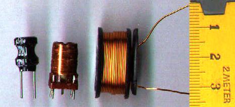
An inductor is basically a coil of wire, which might or might not be wrapped around a metal bar or rod, or some other cylindrical object. You often see inductors in a circuit as coils of what appear to be bare copper wire, wrapped around a cardboard or plastic core. The copper is not actually bare; it is coated with a thin enamel insulation, similar to enamel paint. The reason enamel-insulated wire is often used for inductors is because it is thinner and allows the coils to be placked tighter, and also because it tolerates higher temperatures than most PVC-based wire insulation. The most frequently seen enamels are either clear, or have a reddish tinge that makes the copper look especially gold or red in color. Unlike nearly every other basic electrical component, inductors can be home-made fairly easily, and electronic supply houses sell prefabricated cores of certain lengths, diamaters, and materials for wrapping copper coils around to make inductors.


Inductors (image from Wikipedia Commons)


Inductors in DC Circuits

So what does an inductor do? The idea is simple: it fights any change in the current flowing through it. If a constant DC current is applied to an inductor, the inductor will, in theory, have little or no effect (the resistance of the wire may act like a low-value resistor). However, if anything causes the amount of current that is flowing to change, the inductor will fight that change. If the current tries to increase, the inductor will limit the rate at which the current can increase. Here's where it gets interesting: It will also limit the rate at which the current can decrease -- if the current tries to decrease, the inductor will actually "suck" current through in an attempt to keep it constant! The inductor does this by developing a voltage across it, from one end to the other, that tries to keep the current constant.

Here's a thought experiment. DO NOT ACTUALLY TRY THIS! Imagine a circuit with a battery connected to a switch and a large-value inductor, all in series. Initially, the switch is off, so no current is flowing. Then, we turn the switch on. What happens? The inductor does not allow the current to go to maximum immediately. Instead, the current ramps up gradually. Eventually, it reaches the maximum current that the battery is capable of supplying, but if we have a really large value inductor, it will take some number of seconds. If we had an ammeter or a scope with a current probe monitoring this, we could see it going up slowly at first, and then faster as it approaches the maximum value.


What happens when we turn the switch off? The current tries to go to zero immediately -- and the inductor doesn't like it one bit! It will develop a LARGE voltage in an attempt to "suck the current through", and very likely it will draw an arc across the switch contacts! This is why I said in the previous paragraph not to try this (unless you have a well-equipped lab and your fire insurance is paid up).

Inductors in AC Circuits

So in a DC circuit, an inductor can do drastic things when large step changes occur in the current, but as long as the current is in a steady state, nothing interesting happens; the current simply flows through. But what about an AC circuit? After all, a fundemental characteristic of AC is that the voltage, and hence the current, is changing all the time. Well, the obvious answer is that the inductor will resist all of the changes in the current, and it will do so in a manner that tends to keep the average current at a midpoint value. If we assume that the waveform is symmetrical, then the average current will be at the midpoint between the top and bottom peaks. If we further assume that the waveform has no DC offset, then that midpoint value is zero. Which means that, in effect, the inductor is acting like a resistor to the AC current.
At this point, we note something about AC. As we know from the Fourier theorem, all alternating signals are made up of sums of component sines. Let's consider two sine waves, both of the same peak-to-peak magnitude, but one of a low frequency and one of a higher frequency:


Low-frequency sine (green) and high frequency (red).
The dashed lines show the maximum slopes.

Note the slopes of the two sine waves where they cross the axis. You can see that the high-frequency one is rising and falling at a greater slope, and hence a faster rate, than the low-frequency one. So if we run both of them through an inductor, what happens? Per our discussion above, the inductor will resist both of them, but it will resist the higher-frequency one more. The inductor is acting like a frequency-dependent resistor, whose value increases with frequency -- which makes it a low-pass filter. You may recall seeing the previous sentence in the capacitors discussion. In fact, in an AC circuit, the inductor does the opposite of what the capacitor does; the capacitor is a high-pass filter; the inductor is a low-pass filter. And you can do, in theory, most of the same things with inductor-based filters that you can do with capacitor-based filters.

However, in reality, inductors are rarely used as filters in modern audio equipment. The reason is that small inductors are only effective in the RF range; an inductor-based filter for audio requires a huge inductor. There are practical problems with large inductors; besides the physical size, weight, and cost in copper, they also have the unfortunate habit of acting like radio antennas. A large inductor will pick up electromagnetic noise from other circuit components and the surrounding environment. (This is actually how a guitar pickup works. The magnet in the pickup sets up a field that is interfered with by the vibration of the guitar's strings. The pickup coil senses this interference and converts it into a signal. And as any guitar player who has played a guitar with non-humbucking pickups will tell you, the pickup coil also senses any other interference in the room and converts that into a signal too.) This is why you don't find many inductors in synths or other audio equipment.

Inductors, Electromagnets, and Applications

One other thing that an inductor does is create a magnetic field. This field is inside the coil and extends from one ends of the coil to the other, and slightly outside at each end. If you put an iron bar inside the coil, then when current is flowing, the bar becomes a magnet. This is precisely what an electromagnet is. If you mount the bar so it can slide in and out of the coil, then when current is flowing the magnetic field will pull the bar into the coil. If you then connect a spring to pull it back when the coil is not energized, you have a solenoid. If you connect a switch to the piece of iron, you have a relay. Relays are useful for allowing high voltage circuits to switch low-voltages ones on and off, or to allow DC circuits to switch AC circuits, or vice versa.

Transformers

If you run AC through the coil, you will obviously create an alternating magnetic field. One thing that an alternating magnetic field can do is induce a current into another coil that happens to be wound around the same core. This is precisely what a transformer is. A transformer is a power-converting device.

Recall that power, measured in watts, is calculated as:
watts = EI
where E is the voltage and I is the current. Now, in the transformer world, they don't use the term watts; they call them "volt-amps", or VA, instead. There's a reason for this that I won't get into; if you've ever heard the term "power factor", it has to do with that. The two coils of a transformer maintain a constant VA; VA in equals VA out. However, the voltage is not constant; it is determined by the ratio of the number of turns in the coils. If the primary coil (the one the power is applied to) has 100 turns, and the secondary coil (the one the current is being induced in) has 50 turns, the ratio is 2:1, and the voltage across the secondary coil will be half that applied to the primary coil. Since the VA is constant, that means the secondary coil will supply twice the current applied to the primary coil. That's how the power supply in a synth steps down the high mains voltage to the low voltages used by the synth circuitry. It's also how the output transformer in a tube amplifier converts the high-voltage signal from the output tube into the lower-voltage, higher-current signal needed to drive the loudspeaker. (And it should be noted that the loudspeaker itself contains an inductor, which creates the magnetic field that moves the speaker cone.)

Specifying Inductors and Transformers

The basic unit of inductance is the henry (no kidding), abbreviated H. As it turns out, one H is a larger amount of inductance than what is generally needed for the purposes for which inductors are used in electronics, so most inductors you will see in electronics parts catalogs will be specified in millihenries, or mH. Inductors will also be rated according to their maximum current capacity.

Transformers are rated in terms of the volt-amp (VA) capacity, and the turns ratio. There is usually also a maximum current rating (which is a function of how the transformer is constructed) and a maximum operating temperature. The turns ratio tells you what output voltage you can achieve for a given input voltage, and from that you can figure the maximum output current achievable, and compare to the transformer's maximum current rating. Transformers often have a multi-tapped coil on one or both sides; some of the taps allow some of the turns on that coil to be bypassed, which effectively changes the transformer's turns ratio. This is common in transformers intended to be used in power supplies; there will usually be taps on the primary side to accommodate both U.S. 120V mains and European 240V mains, and there may be a third one for Japanese 100V mains. If the device containing the power supply is taken to a different part of the world, it can be adapted to a new mains voltage by moving the power input lead to a different tap, or perhaps through a switch arrangement which accomplishes the same thing. Some transformers also have multiple taps on the secondary side, that allows the transformer to supply two or more secondary voltages in one unit. Remember that transformer depend on an alternating magnetic field being set up by the primary coil, and so they only work with AC voltages.

Summary

That's as far as I'm going to into this topic. There's a lot about inductors that I've ony hinted on, because the topics are more relevant to power engineering than they are to electronics. But if you are interested, do some Internet searches on the terms "reactance" and "power factor". As it turns out, when you get into these topics, you will discover that capacitance and inductance are two sides of the same coin, and there is some hairy but interesting math that arises.

Saturday, May 9, 2009

Electricity for Synth-DIYers: Capacitors

The next electrical component we're going to talk about is the capacitor. A capacitor is basically a storage device for electric charge. It's somewhat similar to a battery, although the analogy only goes so far: a battery stores electrical energy by converting it to and from chemical energy. A capacitor does not do that; it simply collects and stores charge.

A capacitor consists of two metal plates, each attached to a conductor, and separated by some type of insulator which is referred to as the dielectric. When the two plates of a capacitor are connected to the two poles of a battery or some other source of DC current, current flows in. At this point we have to talk about electrons, since they are the charge-carrying particles at the atomic level. Recall that the charge of the electron is negative, and that the flow of electrons in a circuit is in the opposite direction of "conventional current" (that is, conventional current flows from positive to negative, but electrons actually flow from negative to positive).


So electrons flow from the negative pole of the battery into one plate of the capacitor. They can't flow over to the other side of the capacitor because of the insulating dielectric. The dielectric won't permit a flow of current through it, but it will allow electrons to collect on its surface. The electrons on the negative side of the capacitor develop an electric field, which repels like charges in the same way that a magnet pole repels the like pole of another magnet. So what happens is that as electrons build up on one side of the dielectric, the electric field shoves electrons off the opposite side to the other plate and then out of the capacitor. That side of the capacitor then develops a positive electric field (absence of electrons). This process causes a voltage to develop between the two sides of the capacitor. This voltage opposes the voltage of the battery, which causes the flow of current into the capacitor to slow down. Eventually the voltage across the capacitor equals the battery voltage, at which point the flow of current into the capacitor stops. The system is now in a stasis condition. No matter how much longer you let the circuit sit there, nothing else is going to happen

Now, remove the battery from the circuit. What we have left is a charged capacitor -- essentially, another battery (although it holds a lot less energy, unless it's a really huge capacitor). If you then have a switch that you can use to collect the two sides of the capacitor together, the electrons will flow back out of the negative (excess electrons) side, through the circuit, and back around to the positive (deficient in electrons) side. As this occurs, the voltage across the capacitor drops. Eventually, the number of electrons on each side equals out; at this point the voltage across the capacitor is zero, and the current stops.

Controlling the Charge and Discharge Time

With a typical capacitor, if there is nothing external to restrict the current flow, the charging and discharging processes will both happen extremely fast. Putting a resistor in series with the cap slows down the charge and discharge rate, which leads to one of the main uses for capacitors in DC circuits: timing. This is commonly referred to as an RC circuit. Here is an RC circuit used to implement a crude form of AR envelope generator:


When the pushbutton switch (the symbol to the right of the battery) is pressed, the top half closes and the bottom half opens.  The battery is connected to the capacitor through the resistor, and the battery charges the capacitor.  As it does so, the voltage at the output goes up gradually.  Releasing the button opens the top half and closes the bottom half.  This disconnects the battery, and it completes a circuit from one side of the capacitor to the other, through the resistor.  The capacitor discharges through the resistor, and the voltage at the output gradually goes to zero.  A variable resistor or potentiometer could be used to vary the charge and discharge rate.  

The amount of time it takes for the capacitor to reach a given level of charge, at a given supply voltage, is determined by the capacitance of the capacitor and the resistance of the resistor; this is called the time constant. For a given resistance, the charge/discharge time is very repeatable, and the voltage to which the capacitor is charged will also be very repeatable provided that the supply voltage is stable. By convention, the time constant is given as the amount of time it takes to charge the capacitor to about 63% of its full capacity, which also means that the voltage across it will be 63% of the supply voltage. The calculation is simple:

time = RC

where R is the resistance in ohms, and C is the capacitance in farads (which we'll discuss further down).  It should be noted that the charge rate is not linear; as the capacitor charges, the opposing voltage begins to push back against the inflow of current, and the charging rate slows down.  As a rule of thumb, it takes 5x the time constant for the capacitor to reach full charge.

Capacitors and Alternating Currents

So far, we've talked about capacitors and direct currents. How does a capacitor behave with an alternating current? Well, let's think about it, based on what we've discussed so far. The distinguising characteristic of an alternating current is that it switches back and forth from current flow in one direction to current flow in the other, and hence the voltage switches between positive and negative. If we place a capacitor between the two poles of an AC source, and assume that we start with the positive-going half, then the capacitor behaves as described previously: it charges until its voltage equals the source voltage, and then current stops. However, when the AC switches direction, it is no longer opposing the capacitor voltage; rather, it is reinforcing it. So the capacitor first discharges, and then charges in the opposite direction. Again, its voltage eventually equals the source voltage, at which point the current stops until the AC changes direction again.

But what if we use a high enough AC frequency that the cap doesn't have time to fully charge before the direction reverses? We find that the AC current never fully stops, except for the actual moments when the AC waveform itself is crossing through zero volts, on the way to the other side. In fact, if the AC frequency is high enough, we find that the current flows in and out of the cap the same as it would if that part of the circuit were bypassed with a wire. It looks like the AC current is going through the capacitor! We know it actually isn't; the electrons can't pass through the dielectric. But the alternating flows in and out behave exactly the same as if they did.

And the higher the frequency of the AC current, the less impedence the capacitor poses to it. Impedence is just a fancy word for resistance in the AC context. The capacitor is behaving like a frequency-dependent resistor -- which is exactly what a filter is. The cap is a simple high-pass filter; it blocks low frequencies (and DC, which has a frequency of zero), and lets high freqencies pass. Nearly all filters used in synthesizers are based on the frequency-dependent behavior of the capacitor. Note that a simple capacitor is a long way from a practical VCF, but it's still the basis of one.

If the capacitor is placed in series with the circuit, it acts as a high-pass filter:


If the capacitor is connected between the circuit and ground (e.g., the negative side of the battery), then it "shorts out" the high frequencies. The low frequencies that can't pass through the capacitor go past it as if the capacitor wasn't there. So, in this configuration, the capacitor acts as a low-pass filter.

When using a capacitor as a filter, it would be nice to know what the cutoff frequency is. The problem with the circuits as shown above is that the exact cutoff frequency is highly sensitive to the small resistances in the wiring of the circuit, the internal resistance of the capacitor (no capacitor has absolutely zero internal resistance), and so forth. We solve the problem by putting a resistor into the circuit. Even a relatively low-value resistor of, say, 500 ohms, will probably be much greater than the parasitic resistances in the circuit, and it will overwhelm their effects. By doing this, we can now use the time constant that we discussed above to calculate the cutoff frequency. Remembering that the time constant is equal to R * C, we have:

Fc = 1 / (2 * pi * R * C)

where R is the resistance in ohms, C is the capacitance in farads, Fc is the cutoff frequency in Hertz (cycles per second), and pi is the familar circle ratio constant, roughly equal to 3.1416. (If you spend time looking at filter formulas and calculations, you will see the constant pi pop up frequently. There are mathematical reasons for this that are too complex to go into here.) Note that RC filters are single-pole filters, with a cutoff slope of 6 dB/octave. Most filters used in synth circuits are either two-pole or four-pole types.

However, there are two important applications for capacitors where we often don't care exactly where the cutoff frequency is: DC blocking and power supply bypassing. All capacitors have the property that, if you have a mixed signal with both DC and AC components, the capacitor can separate the DC from the AC. One place where we often want to do this is in the inputs and outputs of various audio circuits. For example, at the input of an audio amplifer, we would like to be able to remove any DC present in the signal. Amplifying the DC serves no purpose; you can't hear it, and large DC offsets in the output can damage the amp or the speakers. Running the input signal through a suitably large-value (a few millifarads) capacitor will block the DC while allowing all of the AC components in the audio frequency range to pass through. On the other hand, in almost any electronic device there are certain circuit components, such as certain ICs, which are connected to the power supply and vary hugely from moment to moment in how much current they draw from the supply. When they do that, they introduce noise into the power supply. This noise can be picked up by other circuit components, and can introduce noise or extraneous signals into the circuit's output, or even cause the circuit to malfunction. Bypass capacitors are frequently placed on a circuit board to take care of this problem. A capacitor, connected between the power supply and the ground (and usually placed near the power pin of the noise-creating IC) will shunt the noise components to ground and get them out of the DC supply.


Capacitors in Series and Parallel

If you remember the discussion of resistors in series and in parallel from that post, you might recall that when two resistors are in series, their values simply add; when resistors are in parallel, they follow the "reciprocal sums" rule. Interestingly, capacitors behave in exactly the opposite way; caps in parallel add, while caps in series follow the reciprocal-sums rule. So if we have three caps C1, C2, and C3:

In parallel: C total = C1 + C2 + C3

In series: C total = 1 / (1/C1 + 1/C2 + 1/C3)

Types of Capacitors

Capacitors may use different types of contstruction and different dielectric materials, which effects the secondary characteristics of the capacitor, such as working voltage and the physical size of the capacitor.  Often the choice of dielectric is a tradeoff between those two factors.  for example, a capacitor that uses air as a dielectric can tolerate high voltages, but a large-value air cap will be physically huge.  A "better" dielectric can accommodate a higher charge density and make a smaller cap, but these dielectrics often cannot tolerate high working voltages.  The types you are most likely to see in electronics are:

  • Ceramic. These use a disc of ceramic as the dielectric. They are fairly stable, tolerate physical abuse, can take high voltages, and are inexpensive. You will see a lot of these used as bypass caps. Main disadvantage: because the dielectric constant of the ceramic isn't very large, they can't be made in high capacitance values; they'd be too large.

A batch of ceramic capacitors, of various values.

  • Metal-film: polypropylene, polystryene, polycarbonate. These are made of a sandwich of the dielectric material, which is a plastic film, with the plates consisting of either thin foil layers or a metal layer vapor-deposited on the dielectric. The whole thing is wound up in a roll, like paper towels, which makes for large-value capacitors that are very small. Polystyrene types are the most temperature-stable, but they don't take high voltages and are hard to find for some reason nowdays. Use these for applications where the exact capacitance value is critical, such as timing and VCO circuits. Polycarbonate is supposed to be second-best in stability, and it takes higher voltages.

A metal-film "box" capacitor, installed in an MOTM module.

  • Aluminum electrolytic. These offer high capacitance value in a given space. They use a paste or gel electrolyte that "forms" the dielectric when a voltage is applied to the capacitor. Most types are polar; they can only take charge in one direction. They appear mostly in power supplies, and in places in circuits where a very high capacitance value is needed and the exact value isn't critical. They lose capacitance value over time, declining to as little as 10% of the original value after 5-10 years. The electrolyte can overheat and leak, or burst the case, if the capacitor is used in the design improperly or if a circuit malfunction apples current to it outside of its design specs, or if the ambient temperature gets too hot. There are "bipolar" types which appear mostly in amplifier circuits as DC-blocking capacitors, and in loudspeaker crossover circuits.


Electrolytic capacitors. The gray ones are polarized; note the back stripe and the shorter leads which indicate the negative terminal. The black one is bipolar.


A large electrolytic that was used as a filter in an amplifier power supply. The gray stripe, just visible at the right, indicates the negative terminal.  Also note that the cap is marked with its maximum working temperature; these types are often used in applications where they get hot.
  • Tantalum. These offer the absolute highest capacitance value in a given space. They have tighter tolerances than the aluminum electrolytic types, and are less sensitive to environmental conditions. They cannot take high voltages, but the main reason they aren't used much in synth DIY is that they are polar, more expensive than electrolytics, and they have a rather distressing tendency to explode if a reverse voltage is accidentally applied.

  • Paper and mica. These aren't used much any more, but you will run across them in antique electronics. The paper types use an oil-soaked paper as the dielectric. They weren't very good. The mica types (mica is a mineral, a sort of natural glass) were very good, but ceramic types have similar specs these days, and mica is expensive. Few paper caps are in production any more; some mica types still are, but there is no compelling reason to use them in synth circuits.

Units of Measurement

The cpaacitance of capacitors is rated in farads, abbreviated F. As it turns out, because of the way the unit is defined, one farad is a huge amount of capacitance. Unless you work in power distribution, you're unlikely to ever come across a capacitor that large. Capacitors used in electronics are usually rated in microfarads (1/1,000,000 of a farad, abbreviated uF), nanofarads (abbreviated nF, 1000 nF = 1 uF), or even picofarads (abbreviated pF, often pronounced "puff", 1000 pF = 1 nF). North American usage tends to avoid nanofarads; caps in that range are usually expressed as a fraction of a microfarad or as thousands of picofarads. Europeans are more sensible and simply use nanofarads when called for. In most synth circuits, you will see caps ranging rrom a few pF up to about 100 uF. Power supplies will use larger ones for filtering, up into the tens of thousands of uF. Note: many mathematical formulas involving capacitors, including the ones in this post, require the capacitance to be stated in farads, not any of the smaller units. It can all be hard to keep track of.

How Capacitors are Specified

The capacitance value is specified in some sub-unit of farads, as described above.  Unfortunately, unlike the case for resistors, there is no really standard way of marking values on capacitors.  Some caps do use a RETMA-like color coding, but most are marked in text.  One system often used on smaller-value (and physically smaller) caps is a three-digit code, where the first two digits are the first two digits of the value in picofarads, and the last digit is a number of zeros to add to the first two digits.  So, for example, a cap marked "102" would be 1000 pF, or 1 nF.  Electrolytics, particularly larger ones, are usually marked with the actual value.  

There is far more variation in capacitor tolerance values then for resistors.  Most ceramic and film types are sold at 10% tolerance; 1% or better are available but are expensive.  Tolerance is often not marked; you have to look at the packaging to know.  Most electrolytics have terrible tolerance specs; +100%, -50% is not uncommon.  (Also keep in mind that electrolytics usually lose value as they age.  These are good reasons to use some other type in applications where the exact value is important.)

Secondary characteristics that are important in capacitors include whether or not the capacitor is polarized, the working peak voltage, the temperature coefficient (how the capacitance varies with temperature), the tolerance, and the equivalent series resistance or ESR. As we have discussed, most electrolytic and tantalum types are polarized; they can be charged in only one direction, and will be damaged if voltage is applied in the opposite direction (dramatically, in the case of tantalums).  The negative lead is usually indicated by a stripe on the body of the cap, or the lead being shorter, or both.

Working voltage is a function of the dielectric and the capacitor's construction. Some types of dielectric have better ability to withstand high voltage than others do. If an excessive voltage is applied to the capacitor, the dielectric breaks down, and then the capacitor shorts out or does something worse, such as burst or catch fire. When considering voltage ratings, you need to consider the peak voltage that the capacitor will be exposed to, and then allow some margin. Rule of thumb is to specify the cap for at least double the expected peak operating voltage. This is frequently fudged down to 50% or less when specifying large electrolytics, due to physical size and cost.

Most types of capacitors vary with temperature. For electrolytics in particular, this can be considerable, to the extent that manufacturers don't always publish data on it. For other types, there are usually several types or grades of variation with temperature. The Electronics Industries Association has a complicated system for designating these. Just know that if you are buying ceramic caps for an application that requires the least available variation with temperature, look for a type designated "NPO or C0G".

Equivalent series resistance, or ESR, can be caused by both resistance and inductance within the capacitor. ESR becomes a factor in circuits where the cap is expected to handle either large currents or high frequencies (1 MHz or above). In synths, you will usually not run into these situations except when dealing with power supplies. In a power-supply filtering application, it pays to get low-ESR types, since these will not get as hot and therefore will last longer. If you are working with digital circuits having high-frequency clock signals, say for a CPU, you may have to think about capacitor inductance, which causes higher ESR at high frequencies. The easiest way to avoid this problem is to stick to ceramic types whenever possible in high-frequency circuits; ceramics nearly always have very low inductance. (In power-supply filtering and decoupling applications, it is often recommended to use two caps in parallel: a film or electrolytic type to handle the higher currents and lower frequencies, and a ceramic to bypass the high frequencies.)  ESR may vary by frequency, and electrolytics often have high ESR at higher frequencies.  For that reason, it is not uncommon to find, in bypass applications, an electrolytic and a ceramic in parallel.  The electrolytic bypasses the lower frequencies, and the ceramic handles the higher frequencies where the electrolytic's ESR is too high.

Summary

Capacitors are fundamental to today's electronics.  It is important to understand them, since they in effect open the door to AC circuits and signal processing the treats different frequencies differently.  


Thursday, April 23, 2009

Adventures in Backlighting, Part 3: The K5m Lives!

So having figured out the cut-to-size EL sheet, it was time to put it to use. Out came the K5m to the workbench. Once I recalled how to open the jigsaw-puzzle case, I saw this:


The half on the left, laying flat, is the front panel. The right half is the rear half. A closer view of the front:


To cram the power supply into the K5m's case, they had to split it into two pieces. The transformers were crammed into a corner of the back part of the case, and the voltage regulators were put on a separate board, which is the tan-colored board on the left in the photo above. This board sits atop the LCD display board on standoffs, and it also contains the backlight inverter, which you can see below as the white box on the right. In this photo, the power cables have been disconnected from th board and it is in the process of being removed. To the right of the inverter, the small connector and (very short) cable that routes the inverter output to the display board is still connected. Note that if you have the keyboard version of the K5, this board is not here, but there is a ribbon cable that runs across the back of the display board. On the keyboard K5, you have to remove one of the panel boards to get the ribbon cable out of the way; see here. On the K5m, once you have the regulator board out of the way, the display board is free and clear.


Below is the back of the display board, exposed. Note the metal clips holding it in around the edge. To remove it, you must get some needle-nose pliers and very carefully bend those clips out of the way. They will only tolerate being bent so many times, and the pressure they provide to hold the board in is essential to the LCD working properly. Don't bend them any farther than necessary to get the board out. The gray ribbon cable at left is soldered in at this end, but can easily be unplugged from the CPU board at the other end. The dark green board below the display board is the panel board.


The top of the liberated display board, showing the LCD screen. The backlight is soldered in at the top end, in this picture. For the moment, we put this aside; we'll get back to it later.


The next step is to remove the dead inverter and retrofit the new one. Whatever brand of new inverter you buy, it's almost certain to not fit in the same holes as the old one. Here's the regulator board with the old inverter removed. The connector on the left is the inverter output going to the display board; the connector in the right is for the raw juice coming in from the power transformers.


Here's the regulator, which I mentioned in part 1. It's a Hantronix HVI-5E ordered from Mouser. It has three pins, in the same pattern as old inverter:
  • pin 1: +5V in
  • pin 2: common (return for both the +5 and the inverter output)
  • pin 3: inverter output, 90VAC @ 400 Hz


To my surprise, pins 2 and 3 of the new inverter actually fit in the same holes on the board. If I could just figure out what to do about pin 1, I'd be golden. I considered bending it over and running a jumper wire over to the hole, on the component side of the board. But then I thought of a cleaner solution: I could tell that the board was a single-layer board (hold up to a strong light if you have any doubts). Could I drill a hole for pin 1? Looking on the back of the board, there were no traces in the area that I had to drill. So I drilled a new hole. In the photo below, the old hole for pin 1 is below and slightly to the left of the drill bit:


Note: do this trick with a circuit board only if there are no traces nearby, and you are absolutely certain that it isn't a multi-layer board! Else you may cut an internal-layer trace, or accidentally short power to an internal ground plane, both equally nasty and non-fixable.

Success! Here's the inverter pins protruding through the back of the board. Note the lack of a pad around one of them; that's pin 1 in the new hole:


It was a trivial matter to install a jumper to connect the pin to the old hole location. Here it is, with the jumper installed and the pins clipped:


And the result. This turned out to be a good solution; the inverter is secure on the board, and the existing connector and cable to the display board are still functional.


Now, on to the actual backlight replacement. This turned out to be more trouble than I was expecting. First, the end of the existing backlight, which is a plastic piece that just slips in the slot between the LCD and the board underneath. It has these two tabs soldered in at the end, which are connected on the board to the cable that goes to the inverter:


Unsoldering the tabs is straightforward. Once that is done, the old backlight is just pulled out of the slot:


Here's what you see with the backlight removed. The grey are is the actual display area of the LCD. Note carefully the rubber strips at the left and right edges. Those rubber strips contain many tiny electrical connectors, which simply touch (they aren't soldered) many equally tiny surface-mount pads on the board. There is some kind of conductive glue holding the rubber strips to the board, and it isn't very strong. Also note that there are some exposed vias underneath the LCD.


Here's our new backlight, cut down to the proper size, and with two strips of conductive-glue copper foil attached to the tabs on the bottom, and crimped at the ends to form contacts. I took it to work and cut it with one of those guillotine-type paper cutters to get a clean edge.


Problem: the old backlight was insulated on the bottom. The new one has exposed conductive surface on the bottom, and we can't let that come into contact with those exposed vias. So I had what I thought was a brilliant idea: I'll just put the old backlight back in, unconnected, and put the new one in on top of it! That way, the old backlight will act as an insulator. It was a tight squeeze, but I crammed it in. Here's the result, with the copper foil tabs newly soldered to the pads on the board. I was so proud of myself...


... until I reassembled the display to the front panel and found that it the LCD no longer worked properly; it displayed black lines across the face, and had rectangular patches that didn't work. I took it back apart, and found that one side of the LCD contact strip had come unglued from the board. When I took it out, the whole backlight arrangement fell out the side! Disaster, I thought. At first, I thought it was unsalvagable, until I realized that since the contacts weren't soldered, maybe if I just put it back together without the stack of the old and new backlights forcing the LCD up, the pressure from the metal tabs that hold the display board in (and the display itself against the front panel glass) would hold it together.

At this point, it occurred to me what I should have done about the conductive backside of the new backlight: simply cover it with electrical tape. This I did, and once that was done, it easily fit back in the slot by itself (it's actually quite thinner than the old backlight). So, starting over from here again:


I was able to slip the new backlight back in, and since the LCD was coming up on one side, I was also able to get my finger in there with a piece of electrical tape to keep the copper foil from touching the board, while getting the tabs on the end of the backlight stuck back on to the ends of the foil tabs. After a couple of false starts, I got it back in there and got the whole thing reassembled, and all of the cables attached again. Here it is, nearly ready to close up; you can see the power transformers on the right:


Every time I open thing thing up, the metal case gets a little more warped and there are a couple of more case screws that won't go back in:


But it works! I can actually see the display again, and the light is a nice white color! Here it is in all of its additive-synthesis glory. (Weird shadows and colors were caused by reflections of ambient light in the room.) I noticed that the very top row of dots on the display is very faint, but I'm not going to mess with it; I really don't want to have to take that display board out again.


Now, while I had this beast open, there were a few other things that I could have done that are recommended for K5/K5m owners. If you go back to where the panel board is mentioned, you can remove that board and clean the button contacts (click on the link and scroll about 2/3 of the way down) to make the buttons work better. You can also upgrade the OS by installing a new ROM available from the Yahoo K5/K5m user group; the latest version for the K5m is 1.2, and for the K5 keyboard is 1.3. (It displays the OS version at boot time.) The ROM is socketed so it's an easy replacement. I had already done the button cleaning on mine in a previous servicing, but I do plan to buy the OS upgrade ROM and open it back up later to install that. And there is a mod to improve the output level (kfuenf again; scroll down to near the bottom); I had also done that previously.

Sunday, April 19, 2009

Electricity for Synth-DIYers: Resistors

As the name suggests, the purpose of a resistor is to restrict the flow of electricity through a circuit. Here's a few things that a synth-DIYer needs to know about resistors.

What are Resistors For?

Resistors are used to control the voltage in a circuit, or to control the flow of current through a circuit. We saw an example of the latter in the first installment of this series, where we used a resistor to limit the amount of current flowing through an LED. Resistors are often used to create a drop in voltage in a circuit. For example, if two resistors of equal value are wired in series between the two poles of a battery, the voltage at the point in between the two resistors will be half the battery voltage; this type of circuit is known as a voltage divider. Unequal values create different in-between voltages.

Resistors can be used to "convert" a current into a voltage. An example often seen in synth circuits is a resistor wired to the output of an OTA, an IC frequently used in analog synts. The OTA produces a specific output current which is proportional to its inputs. By placing a resistor on the output, a voltage is developed in between the OTA output and the resistor which is proportional to the OTA's output current.

A pull-up resistor is used to apply voltages to the inputs of components which act as electronic switches, such as JFET transistors and bilateral switches. The switch has an "open" or "closed" position, but in order for another circuit to sense that, some voltage must be applied to the switch input. A pull-up resistor between a supply voltage and the switch input provides the necessary voltage. With the output of the switch connected to ground, when the switch is closed, the measured voltage at the switch input will be zero. When the switch opens, the voltage at the switch's input will rise to the supply voltage, due to the pull-up resistor. The pull-up also limits the current when the switch is closed; otherwise, the switch would short out the supply voltage.

Similarly, a resistor wired between a voltage source and ground acts as a "pull-down". A high-value resistor is often wired to the external input of a circuit to provide some protection against static charges. Static electricity may have very high voltage, but very low current. A high-value resistor dissipates the static charge without "loading down" the circuit's normal input signal.

A resistor in series with a capacitory has an effect which is similar to reducing the capacitance value of the capacitor. This will be covered further in a later installment.

Ohm's Law

The degree to which a resistor resists is measured in ohms. The definition of an ohm is: if a voltage of one volt is applied to a resistance of one ohm, a current of one amp results. This leads to a basic formula of electricity, known as Ohm's Law:

E=IR

where E is the voltage, I is the current, and R is the resistance. (Why is E the voltage and I the current? E comes from an old term for voltage, "electromotive force". You do sometimes see the letter V used instead. "I" for current, I have no idea, other than the fact that "C" was already taken for something else.) Of course, you can do simple algebraic manipulations to find any quantity needed, given the other two; for example, if you know the voltage and the resistance and you want to find the resulting current, divide both sides by R, and you get:

I = E/R

Specifying and Choosing Resistors

In specifying resistance values, the ohm is represented by the Greek letter omega, which is: Ω. The usual metric multiplier prefixes can be added to this for larger values, for instance, 6 kilo-ohms would be written as 6kΩ, or sometimes just 6k if the context is understood. One ohm isn't much; typically, in electronics about the smallest resistance one encounters is 100Ω, and resistors with values in the megaohms range are sometimes called for. In practice, the omega symbol is often omitted when it is understood from context. A convention that is sometimes seen is that the resistance value will be written with either the letter "R" or the metric multiplier prefix placed in the number where the decimal point would go. So for example, 100Ω might be written as 100R; 1000Ω would be written as 1k, and 6800Ω would be written as 6k8.

Two other parameters are commonly given in specifying a resistor: the tolerance and the maximum power dissipation. Resistors are mass produced, in very large quantities, and the manufacturing processes are not perfect. As a result, it's actually rare for a resistor to measure as being exactly the specified value; it may be some small percentage more or less. Manufacturers measure and grade their resistors as to how close to the spec value they actually are, and then "bin" them up into tolerance ranges. As one might expect, the tighter tolerance ranges cost more. The most common tolerance range sold today is 5%, meaning that if a resistor is marked as a 10KΩ, 5% resistor, its actual value may be anywhere from 9500Ω to 10,500Ω. Besides 5% resistors, the other commonly available ranges are 1% and 0.1%. Electronic products built prior to about 1980 may contain 10% resistors, but resistor manufacturing processes have improved to the point where the 10% range is no longer marketed much, since there is no cost savings. When designing a circuit, the circuit designer will determine for each resistor in the circuit how much tolerance is allowable in order for the circuit to work, and then specify the tolerance based on that information.

Power Dissipation

Whenever a current passes through a resistor, some of the energy contained in that current is converted into heat. A resistor can only dissipate so much heat before it reaches a high enough temperature to destroy itself or nearby components. This waste heat, along with all other measures of energy and power production in the electrical world, is measured in watts. Note that the watt is not a quantity of energy; that's a common mistake. It is rather a rate at which energy or power is produced, flowed, or consumed. (In order to drive your car down the highway at a given miles or kilometers per hour rate, the engine must produce power at a certain rate. That rate of power production can be measured in watts, although in the case of automobile engines, "horsepower" is usually used instead. Horsepower is simply a different unit for the same thing: 1 horsepower roughly equals 750 watts.)

The power dissipated as heat will of course raise the temperature of the resisitor. To avoid cooking the resistor, the dissipation needs to be kept below the rating. If you know the voltage across the resistor and the current flowing through it, the dissipation is given by:

Watts = EI

Many times, in circuit design, you won't know the exact current, only the voltage applied to the resistor. Using Ohm's Law, you can substitute for I in the above:

I = E/R

so,

Watts = E(E/R) = E^2/R

The most common dissipation rating for the types of resistors used in electronics is 1/4 watt. 1/8 watt and 1/2 watt types are also common. In general, the dissipation rating is directly proportional to the physical size of the resistor. Types rated for more than 1 watt are usually large and difficult to package; they are also often built as "wirewound" types which have other effects on a circuit that must be taken into account in the circuit design.

Substituting Resistors

A few rules of thumb for resistor substitution:

  1. You can always use a resistor of tighter tolerance than specified. If a parts list calls for a 5% resistor, you can use a 1% or better resistor of the same value.

  2. You can use a higher-dissipation resistor than specified, provided that it physically fits in the space where it needs to go, and as long as you avoid wirewound types. If the parts list calls for a 1/4 watt resistor, a 1/2 watt or 1 watt one will work as long as it fits on the board. Don't use wirewound resistors unless the schematic specifically calls for it.

  3. If you are in a pinch for a resistor value you don't have, or if you need an oddball value, you might be able to assemble using some combination of series and/or parallel resistors; see the next section.
Resistors in Series and in Parallel

Sometimes, you need a resistance value that is not a standard value or not easily available. You can build different values by wiring up two or more resistors in series and parallel. The rule for combining resistors in series is simple: their resistance values add. Example: a 10K resistor in series with a 6.8K resistor adds up to 16.8K. Resistors wired in parallel are more complicated: the rule there is often called "reciprocal sums". Suppose you have three resistors, R1, R2, and R3 in parallel. You first take the reciprocal of all of their values and add those:

1/Rsum = 1/R1 + 1/R2 + 1/R3

Then, take the reciprocal of 1/Rsum to get the result. So, for example, if R1 = 1K, R2 = 2200 ohms, and R3 = 5000 ohms, the calculation is:

1/Rsum = 1/1000 + 1/2200 + 1/5000

1/Rsum = 0.001 + 0.00045 + 0.0002 = 0.00165

Rsum = 1/0.00165 = 604 ohms

Note that the resulting value is less than the lowest-valued resistor in the set. This will always be true for resistors in parallel. The technique can be extended to any number of parallel resistors. Simplification: if all of the parallel resistors have the same value, the result will be that value divided by the number of resistors.

To figure the dissipation of series or parallel resistors, you would have to work out the applied voltage for each resistor, which can be some work. Try this shortcut first: figure the dissipation treating the resulting value of the series or parallel combination as if it were a single resistor. If that is within the dissipation of all of the resistors in the combination, then it's okay.

Resistor Markings

Resistors often do not have their value printed on the resistor body; instead, they use what are known as the RETMA codes, which are the colored rings you see painted on the resistor body. In current usage, this will be a sequence of four or five color bands. Four bands, with one of them being a gold or silver band, indicates a 10% or 5% tolerance. To determine the value, orient the resistor so the gold or silver band is on the right. Then, read the other bands according to this code:

0 = black
1 = brown
2 = red
3 = orange
4 = yellow
5 = green
6 = blue
7 = violet
8 = gray
9 = white

For a 10% or 5% type, the first two bands indicate the first two digits of the resistance value. The third band indicates that the specified number of zeroes should be added on (Note: this is not the same thing as specifying a power of ten! Some resistors use more digit bands, and the same color last band indicates a different power of ten on these. To keep it straight, don't worry about powers of ten; just add on the specified number of zeroes.) So, for example, a resistor with the color code orange/green/red indicates:

orange: 3
green: 5
red: 00 (two zeroes)

The value is 3500 ohms. A gold band at the end indicates it's a 5% tolerance; a silver band indicates 10%.

1% and better types will have five bands instead of four. It can be a bit difficult to determine which end is the left and which is the right, but if you know the type, a brown band at one end will indicate a 1% type. A violet band indicates a 0.1% type; other values are possible. Read the other bands the same way: red/red/violet/orange indicates:

red: 2
red: 2
violet: 7
orange: 000 (three zeroes)

This is a 227K ohm resistor. Below are pictured five resistors. See if you can make out their values.


Top: violet (hard to see in the photo), green, brown, gold = 750 ohms, 5%, 1/4 watt. Second: red, red, red, gold = 2200 ohms, 5%, 1/4 watt.
Third: orange, yellow, orange, gold = 34K ohms, 5%, 1/2 watt (note larger size).
Fourth: red, red, yellow, gold = 220K ohms, 5%, 1/4 watt
Bottom: brown, black, green, gold = 1.5M ohms, 5%, 1/4 watt

Below are some 9.09K, 1/4 watt, 1% types. Note that they use a printed designation instead of the RETMA markings. This seems to be the way the high-precision types are going.


Here are some old 10% types -- note the silver stripes. You don't see these much anymore.


Specialized Resistors

We mentioned wirewound resistors earlier. You normally want to avoid these because they have a property called induction, which will be covered in a later installment. The induction can mess up the circuit that the resistor is in. You will seldom need one of these in music gear, but there is one place where you may run into one -- amplifiers. Reason: wirewound resistors can be made to tolerate very high dissipations, 5W and up. These are often called "power resistors", and sometimes they are needed to control the high currents found in a high-power amp.

A specialized type often found in synthesizers is the temperature-compensating resistor, or "tempco" for short. All resistors are somewhat temperature-dependent. But a tempco's resistance change at different temperatures follows a very specific formula. This can be used to compensate for other circuit characteristics that change with temperature. All VCO circuits that have volts/octave response need a circuit called an "exponential converter" to transform the input control voltage to drive the oscillator core, but the implementation that is generally used in analog VCOs is very temperature-sensitive. A tempco is essential to offset this in order for the VCO's tuning to remain stable as the circuit heats up.


Summary

Resistors are one of the most frequently used of the electrical components. They are available in a huge array of types and values. Sorting out the markings can be tricky, so look closely. If you have trouble remembering the color codes, there are "RETMA" calculators that have little wheels where you can dial up the colors and it will tell you the value.

Next installment: capacitors.