Iris is a plug-in from
Izotope, a company that's better known for products like Trash, Stutter Edit, and "make my track the loudest thing on the dial" mastering tools. Despite what that might suggest, Izotope has a lot of background in
Fourier analysis and spectral processing tools, and they put most of it into Iris. The difference is, with Iris, you get to control it yourself.
Iris employs a method of synthesis whose availability to the masses is relatively recent, and that I had no previous experience with -- spectral editing. So when I first installed it and fired it up, I wasn't at all sure what to expect. But I have been pleased, if at times a bit baffled, at the results I've gotten so far. With that said, let's dig in.
Spectral Editing
What exactly is spectral editing? Well, it involves taking a sample of a sound, and picking out bits of its spectrum over time that you want to reproduce, excluding the rest. Iris presents a sample that you choose in a two-dimensional window, with time on the horizontal axis and frequency on the vertical axis. Energy at a given time/frequency coordinate is represented by a pixel on the screen, with the brightness of the pixel indicating how much energy is present. You use various methods of selecting regions of the time-frequency space that you want to reproduce. Then, when you play the note, it reproduces the regions you select.
The User Interface
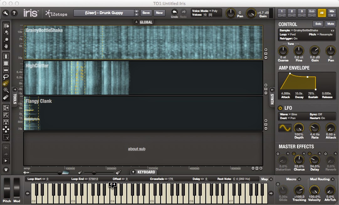
Here is a shot of the screen you are presented with when you first start the plug-in:
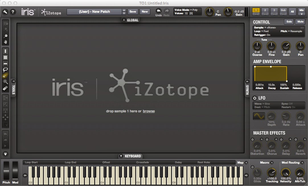 |
| Iris initial view |
The big window with the Izotope logo is where you will load a sample to edit. The toolbar over to the left consists of drawing tools that you use to select regions to be reproduced. The controls on the right allow you to select a layer, tune an edited sample, set up an amplitude envelope for the layer, and route modulations. For each patch, Iris allows up to three layers, plus a "sublayer" which uses fixed waveforms but still allows for spectral editing.
The buttons at the top right switch between different views, or presentations of the user interface. Any of the three layers or the sublayer may be selected for editing by clicking on the "1", "2", "3", or "Sub" buttons. There are two other views available
by clicking their buttons at the upper right of the window: the All view
and the Mix view. We'll discuss these views later. For now, we'll concentrate on the single-layer view, which is where you will probably do most of your work.
Sample Loading and Manipulation
When you load a sample, either by dragging and dropping one into the window, or by selecting one from Iris' library via the browser, you are presented with a window that looks like this (click on the image to see a full size version):
(If you have a copy of Iris, the above sample is "SK8 Circuit Singer".) What you're looking at here is a spectral energy (or power, if you want to think of it that way) display.
Note the frequency scale along the left edge; it indicates that this sample has its highest-energy bands in the 1.5/2.0 KHz range. If you look at the right side of the on-screen keyboard, you'll see a little tag at F#6; this indicates what the sample's "natural" note is, i.e., at what note the sample will play back with no pitch shifting. You can click and drag this tag to change the setting.


Immediately above the sample window you can see a gray bar (shown above this text) with an arrow at each end. You use this to set start, stop and loop points (although Iris will do it automatically, as will be explained later). This is all fairly conventional and similar to other types of sample editors; it allows for one-shot, forward looping, and alternate forward-and-back looping. The bar above this graphically portrays the sample's amplitude envelope, and the gray region indicates the bounds of the currently selected loop, which may be different from where the arrows are set if Iris has chosen the loop points automatically. Below and to the left of the screen are rulers; the one on the left (see to the left of this text) displays frequency, and the lower one (below the next paragraph) displays sample word counts. You can scroll the view horizontally and vertically by grabbing one of these rulers and dragging it.
(If the rulers don't appear, click on the wrench icon at the upper left
to bring up the preferences dialog, and click on "Show Time Ruler"
and/or "Show Freqeuncy Ruler", as you prefer. You can also choose time
or number-of-samples scales for the time ruler, and there are several
choices of units for the frequency ruler.)
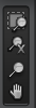
Other tools for view manipulation are at the top left corner. When you click on the top one (the one that looks like a screen with a magnifying glass over it), it zooms in or out enough to show you all of the drawing that you have done in the layer. The second one (the magnifying glass with an X) does a full zoom out and shows you the entire sample. The third one is an arbitrary zoom tool; when you click on it, you can draw the diagonal of a rectangle that you want to zoom in on. The hand tool at the bottom is a scroll tool; click on it, and then you can grab and drag the content of the window.
Editing
(A note here: Izotope refers to edited/painted regions of spectral content as "selections". To avoid confusion with the conventional use of the word "selection" in computer UI phraseology, I'm avoiding the term here; I'll refer to such areas as drawn/painted regions.)
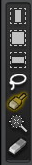
You actually choose spectral content to be played by drawing in the window using the tools from the center left margin (shown to the right of this text). A better analogy for most of the tools is actually painting; you move the tool and as you do so, it paints a certain area which is to be played. The three tools at the top select rectangular areas. The top tool paints a region of time; you choose the tool and then drag horizontally across the time band you want, and it paints all frequencies within the time band. The third tool does the same for frequency bands; you drag up or down and it paints all content across time within that frequency band. The middle tool selects as rectangular area.
(When you first load a sample, before you paint anything, if you play a note you will hear the unedited sample. This is turned off when you do your first painting operation on the sample. If you paint an area and then erase it, so that nothing is painted, you will hear nothing.)
The fourth tool, the brush tool, allows areas to be painted freehand. Click and hold and move the mouse around to paint. Painting is additive, so if you paint over any areas that are already painted, nothing happens. You will notice when you select the brush tool that a slider control appears above the on-screen keyboard, just to the left of the word "KEYBOARD". This allows you to set the brush diameter.
The bottom tool in the tool selection is the eraser. It works similarly to the paintbrush, except that instead of painting, it un-paints already painted areas. The size slider also works with the eraser.
The lasso tool allows you to cause an arbitrary-shaped area to be painted by drawing a boundary around it. Click and hold and freehand the boundary. If you don't complete the loop, it will be completed for you with a straight line connecting the start and end of your draw when you let the mouse button up.
The remaining tool is the "magic wand" tool. This is a bit hard to explain and I don't quite have a handle on exactly what it does. When you use it to click on a painted region, it will select content that is harmonically related and coincides in time with the region you selected. So far, for me it's a "try it and see what it does" thing.
The next set of tools allow you to make bulk changes to the areas you have painted. Iris maintains an idea of the bounds, with respect to frequency and time, of the areas you have painted. When you click on the first one (with the horizontal areas) it inverts all of the painted and un-painted areas within the frequency bounds of where you have drawn. Similarly, the tool with the vertical arrows inverts within the time bounds. The one with the diagonal arrows inverts across the entire sample. The last two tools, with the four arrows and the box with an X, paint or un-paint the entire sample, respectively.
The two tools below that are the undo and redo buttons for painting and drawing. The bottom tool is a preview button; it plays the spectral-edited sample without any pitch shifting.
An example of an edited sample:
Note the four painted regions, including the narrow one at the bottom, and the two vertical dashed lines that indicate the loop start and end points. These illustrate the results with various drawing tools: The area at the left was freehanded; the area at the lower right was drawn with the lasso tool, and the area at the upper right was drawn as a rectangle and then attacked by the eraser.
Brushes and Erasers Don't Scale with Zoom
Note that when you zoom in or out in the view, the size selection for the brush and eraser tools doesn't scale; it remains the same on-screen width at all zoom levels. This means that if you paint a line, zoom in, and then paint another line, the second one will be narrower than the first one.
Auto Loop Points Adjustment
Whenever you do any drawing or add or alter painted regions, the sample loop points automatically move so as to move the leftmost and rightmost edges of all the painted regions. This is done to eliminate periods of silence that would result if the entire sample were played. Refer back to the above figure and notice how Iris has automatically set the loop points in this example, as indicated by the vertical dashed lines, and gray area in the waveform display above the editing window. You can override this and set the loop points manually if you wish, and you can also set the sample start point independently of the left loop point.
Dragging Painted Regions
When any of the above drawing tools is selected, except for the eraser or magic wand, moving the cursor over an existing painted region causes the cursor to change to a hand icon. When this occurs, you can grab and drag the region that the cursor is positioned over. Note that Iris keeps track of contiguous painted regions, as indicated by the crawling dashed lines surrounding them, and it updates these each time you make a change; touching or overlapping painted regions will be combined for dragging purposes. Also note that dragging moves the region, not the sample content underneath.
The Undo Trap
You might notice that there are two sets of undo buttons on the user interface: one down near the bottom of the left margin, above the preview button, and another set at the top margin to the right of the patch selection controls. The ones on the left, you can use to undo and redo drawing operations. Beware of those ones at the top. They undo operations like sample selection and parameter changes. If you select a sample, do a bunch of spectral editing on it, and then hit the undo button at the top of the window… it will de-select the sample and you'll lose all the drawing you've done.
Layer Controls
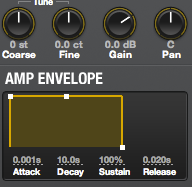
There's a small set of layer controls for each layer, corresponding to other layer-specific features. The four knobs above the amp envelope allow you to set tuning for the layer, control its overall volume, and pan it in the stereo image (the samples are all mono). Each layer has its own amplitude shaper; the amplitude envelope is an entirely conventional ADSR envelope, which you set up graphically by dragging on the little squares. Each layer has an LFO which can be routed to pitch or amplitude (you make it active by clicking on the little power-button symbol next to the word "LFO"). You can set the effects sends for this layer or for the whole mix, depending on the effects mode; I'll say more about this further down.
Several significant controls are in the text box under the word "CONTROL". Clicking next to the word "Loop" allows you to choose the loop mode for this layer. Forward, reverse, alternating, and one-shot in either direction are available.
The "Pitch" item is a pop-up menu with three choices. Iris' normal mode for sample playback is to pitch the sample by speeding up or slowing down playback, the way that early hardware samplers did (this is misleadingly labeled "Resample" in the menu). This of course means that the sounding of a higher-pitched note will be compressed in time compared to a lower note. Choosing "Radius RT" engages a pitch-shifting algorithm that makes all notes play back in the same amount of time. On my i7-based Mac Mini, I found the Radius RT default settings, and the user manual, to be excessively cautious about CPU usage; the manual warns that the pitch shifting algorithm is CPU intensive and accordingly the factory default is to only allow 4 voices at a time to use the algorithm. However, with four notes playing on a layer set to Radius RT, I didn't observe CPU usage to increase much, and I was able to boost the max voices up to 10, and the octave range to +/- 3 octaves, without any problems. I would not hesitate to use Radius RT for any patch where I wanted the playback or loop time to be constant. (On the other hand, allowing loop times to vary with pitch can add thickness to sustained chords and help cover up naff loop points.)
Retrigger mode prevents new notes from starting at the beginning of the sample when playing
legato. In mono mode, you can use it to play legato and the new or retriggered note will pick up the playback at the point where the first one was. In poly mode, it's a bit strange: If you set up the amp envelope with a long release time and turn retrigger mode off, and then play and hold one note while playing a second note, the second note will began playing at whatever point the first note is at in its playback when you struck the second note. Of course, if you are in resample pitch mode, they won't stay together because one will play back faster than the other.
To the right of the word "CONTROL" are mute and solo buttons. These work similarly to on a mixer. If you hit "Mute", the current layer is muted. If you hit "Solo", every layer other than the current layer is muted. A muted layer is indicated by its layer button turning red.
The modulation routing controls at the bottom right are not specific to the layer; they are global. We'll talk about modulation later.
Views
There are three basic views available in Iris. The layer view we've already reviewed above; it allows you to see a single layer at a time and perform spectral editing. There are two other views available by clicking their buttons at the upper right of the window: the All view and the Mix view.
 |
| The "All" view |
The All view is similar to the individual layer view, but it displays small versions of all four layer samples in four panes in the sample editing area. You can scroll these up and down using the small buttons to the right of the panes, or grab and drag the frequency rulers. You can actually do spectral editing in these panes, although it's awkward due to the small size. (Recall what we said a while ago about the painting tools not scaling with the zoom level.) This view contains the same patch parameter settings on the right side as the individual layer views. You choose which layer they effect by clicking in its pane in the sample viewing area.
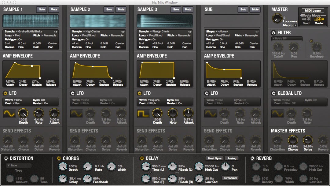 |
| The Mix view |
The Mix view shows all of the patch parameters for all four layers, plus the global patch parameters and effects settings. The sample view area shows only an overview of the sample with none of the spectral editing, and you cannot edit here. However, you can change all of the patch parameters. The area on the right contains the filter controls and the global LFO settings, plus the effects mode setting and the MIDI Learn button, which are only accessible from this view.
The filter effects the overall mix, including the outputs of the effects. There are 11 algorithms; three each of low pass, bandpass, and high pass, plus a peak booster (a sort of very narrow bandpass). Most of them sound like they are intended to emulate familiar analog filter circuits. Cutoff and resonance are adjustable on all, plus there is a dedicated ADSR envelope that can modulate cutoff.
Modulations
Each layer has an LFO that can be routed to pitch, amplitude, or pan for that layer. These are the only parameters that are modulatable on a per-layer basis. Seven waveforms are available, and the onset of the LFO can be delayed using the "attack" parameter. The rate can be synchronized to tempo. When "Restart" is on, the waveform starts at zero for each note played; when it is off, the LFO is free running and all voices will have their LFOs synchronized in phase. There is also a global LFO which can be assigned to global amplitude, global pan, or the filter cutoff frequency. The global LFO's controls are in the Mix view.
The "Mod Routing" controls at the bottom right control global routing of velocity and aftertouch (they cannot be routed on an individual layer basis). Clicking on the arrow symbol next to "Mod Routing" brings up a pop-up window that allows velocity and aftertouch to be routed in varying positive or negative amounts to amplitude, depth of the global LFO, filter cutoff, and filter resonance. Note that all of these are global parameters that apply to the whole patch.
If this all seems a bit limited, it is. The saving grace is that almost every parameter that is visible in the Mix window can be assigned to a MIDI continuous controller. In the Mix window, click on the "MIDI Learn" button at the upper right, and all of the assignable parameters turn blue. Click on the parameter that you want to assign. Then, send a controller message by moving the controller of your choice (or programming it into your DAW), and Iris will associate that controller # with that parameter.
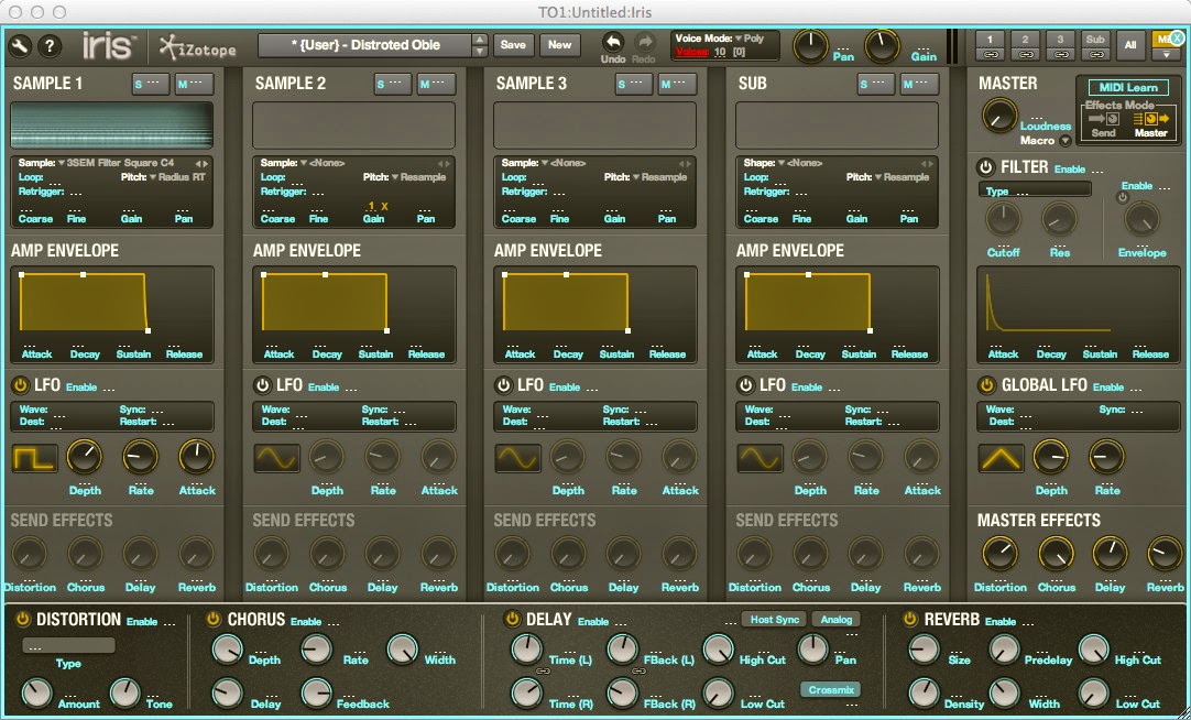 |
| Mix view in MIDI Learn mode |
Effects
There are four effects: distortion, chorus, delay, and reverb. Only one instance of each is available. The effects can be configured in either of two modes: send effects, in which each layer can be routed to one or more effects, and master effects, in which the combined mix is routed through the four effects in series. In order to change the mode, you must select the Mix view. Then at the top right, to the right of the word "MASTER", there is a box labeled "Effects Mode" with icons for the two modes. Click on the one you want.
In Send mode, the Send Effects knobs on each layer allow you to send some amount of that layer to the effects; they work like effects sends on a mixing console. A mix of one or more layers can be sent to each effect. The effects outputs are mixed with the dry outputs of the layers to form the sum output. A slight annoyance is that before you can use an effect, you must click on the power-button icon to activate the effect. A convenience is that, from the layer views, you can click on the arrow icon to the upper right of the knob to bring up a pop-up window that allows you to adjust the effects parameters without having to go to the Mix view.
In Master mode, the four effects are in series: the distortion effect receives the summed dry mix of the four layers, and then the signal flow proceeds from left to right as shown in the mix view. In this mode, the Master Effects knobs, as shown in both the layer views and the mix view, control the dry/wet balance for each effect; if the knob is at zero, the signal will effectively bypass the effect. There is no way to control the balance of individual layers in the effects send when using Master mode.
The quality of the effects is decent. I actually found the distortion effect to be the most versatile. It allows the choice of five different distortions, ranging from the fairly mellow "Tube" to the absolutely brutal "Asymmetrical", plus an aliasing effect that did particularly interesting things to higher frequencies. The chorus is basic but functional and pretty effective for adding some depth to some of the flatter-sounding patches. The delay is also basic but it does what it is supposed to do, and it has a max delay time of 1.5 seconds on each stereo channel. The reverb was the only effect I didn't care for; I found it cloying and limited, and it tended to obscure the more subtle aspects of patches. (As you are going through the factory patches, try listening to some of them with the reverb off.)
Macro Knobs
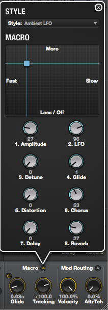
At the lower right of the screen, in every view except the Mix view, next to the modulation routing knobs is a mechanism called the macro knobs. This allows you to assign a number of parameters which can all be changed by turning a single knob. Minimum and maximum ranges can be assigned on a per-parameter basis, and the range can be inverted so that a given parameter can be made to decrease as the knob is turned up, or vice versa. To access the knobs, you click on the pop-up icon next to the word "Macro".
The macro facility comes with some templates, called "styles", with pre-assigned parameters, or you can create your own using the parameter's pop-up menu. The way you do this is: locate the parameter you want to assign, then bring up the parameter's pop-up menu (right-click on Windows, control-click on OSX), and using the "Assign" menu. There are eight macro knobs available (which you can name, on a per-patch basis). Right-clicking or control-clicking on a macro knob brings up a pop-up menu, in which you can change the knob's name, look at the parameters assigned to it, or clear the existing assignments. (If you want to remove just one assignment, or update the range on an existing assignment, you need to go back to that parameter and access its pop-up menu.
The X-Y pad doesn't seem to work quite the way that the instructions describe. It seems to describe the two dimensions of the pad cursor movement being two additional macro knobs, but what I'm seeing is that they are hard coded to the #1 and #2 knobs -- moving the pad cursor horizontally causes the macro knob #1 to increase and decrease, and the vertical does the same to knob #2. The only thing about the pad that I see you can change is the four legends; right-click or control-click on the pad to bring up a pop-up that will let you rename them.
Izotope describes the macro knobs as being a way to quickly achieve a certain style of sound, by choosing the appropriate template, once you have chosen a patch. I'm not actually sure that's the best use for them. Yes, it may be handy sometimes for that purpose, but I see a lot more potential in using them for on-the-fly patch morphing and automation / MIDI control weirdness. The key to this: You can assign a macro knob to a MIDI controller using the MIDI learn mode. To do that, go to the Mix view, and then find the cleverly concealed pop-up icon for the macro knobs -- it's in a different place in this view, to the lower right of the Master knob. After you've done that, you can click on the "MIDI Learn" button, and then you can assign a MIDI controller to a macro knob the same way as for the other parameters.
Conclusions
Iris is a pretty cool piece of software. This is the sort of thing for which soft synths really stand out: a synthesis method that would be all but impractical to implement in dedicated hardware, because of the cost of designing it and the need for a screen to do the editing. I've done a lot of playing with it and I feel like I've only scratched the surface; it's a totally new method of synthesis to me, and I have a lot to learn yet. The edit rendering seems to work well, without any aliasing or Fourier analysis artifacts that I've noticed. The effects, as noted above, are good with the exception of the reverb which I'm not a big fan of. I do wish there was more flexibility in the effects routing.
I only have a couple of criticisms of my own. My main one is that I don't understand why, in this day and age and in this context, the envelopes are restricted to ADSR; the standard for advanced soft synths these days is multi-segment envelopes, and Iris is one synth that could particularly benefit from them. The envelopes would also benefit from both a start delay and a time limit on the sustain phase, which would allow samples to be layered in and out on sustained chords and drones.
I would like to see more drawing tools offered for the spectral editing. Circular and elliptical shapes could be useful, as well as the ability to draw arbitrary polygons by point-to-point clicking. Similarly, the ability to erase by some means other than just freehand is desirable; I'd like to see an "anti-paint" function which works like region painting, but has the effecting of erasing any painted areas that are anti-painted over, and is capable of performing any draw operation that painting can.
A lot of the commenters at
KVR would like to see a time stretch function that can be applied to samples, so that loops can be set up to exact lengths. I haven't found a pressing need for that, though; if I need a sample time stretched, I can export it to some other software to do that job. However, the ability to set loop start and end points to exact times would be helpful. I'd also like to see the ability to set up a separate release loop, like some samplers have.
Another common request at KVR is to be able to set a volume level on a painted region, so that some choice in between full off (not painted) and full on (painted) is available for a region. Not sure what I think about that... I think that if there were multi-segment envelopes, it would go a long way towards fulfilling the same purpose.
I will say that, running Iris as an AU plug-in under Metro [version] on OSX [version], I have found the software to be completely stable. I have encountered no crashes, no functions that ceased working after a while, and no audio or visual glitches. Iris integrates well with this uncommon DAW software, so the software engineers must have done their homework regarding the AU specification. I have also run the stand-alone version and encountered no problems. I have not tried the VST installation -- although Metro accepts both, when I have a choice, I go with the AU version unless it doesn't work for some reason.
Sound Samples
All of the below are uncompressed WAV files, so they may take a few seconds to load.
- Factory patch: Black Galaxy. Demonstrates Iris' capability for creating slowly evolving sounds.
- Factory patch: Toddler Squarepusher. Chosen mainly because I liked the name, and it does fit.
- My patch: Zombie Alarm. Shows the ability to do rhythmic repeating sounds.
- My patch: Coffee Jackhammer. Just plain screwy.


