
Wednesday, December 28, 2011
Washington
A new Statescape... named Washington, and done entirely with the Solaris. More at the Web page.
Monday, November 14, 2011
Solaris demo, and a few comments/corrections from John Bowen
First of all, John Bowen has sent along some corrections and additional notes to my overview posts. (I warned everyone that it was a quickn-dirty...) John's notes:
The mixers allow each input to be modulated separately, plus the output can be modulated. So each mixer allows five different modulation inputs. I should have realized that; I guess I assumed that "ModSrc1:", "ModSrc2", etc., referred to the four mixers rather than the four inputs of the selected mixer.
The S/H waveform of the multimode oscillator is tunable and can track the keyboard; it isn't just a low pass filtered noise.
Samples cannot be loaded via the USB interface in the current version of the OS. To get new samples into the system, what you have to do is get a CF flash card reader connected to your computer (they're cheap), pull the CF card from the Solaris, put it in your reader, and then move the sample files to the card. Then, you plug the card back into your synth. I'll write some more about samples and sample loading after I've had a chance to experiment with it.
I forgot to edit something before I published it about signal routing to the FX channels, and as a result I got that part wrong. The four VCAs mix down into a fifth VCA, which you can't control directly, but VCA 6 is connected to it. When you select "synth" as the input to an FX channel, it is taking its input from the fifth VCA.
The overdrive part of the Minimoog filter algorithm was actually moved from the filter to the VCA section, which allows you to use overdrive with any filter. It's the VCA "boost" parameter (which I missed when I read that in the manual).
I mentioned some anomalous behavior in the velocity and aftertouch, which at the time I was writing that post, I had confirmed with MIDI Monitor. Well, guess what: the next day, it was behaving normally with the same patches. So I'm not sure how I did that. Possibly I messed up the sensitivity settings when I was playing with the system parameters (which, fortunately, I didn't save).
The envelope follower can be used with any signal source, not just the external inputs. I knew that, but the way I wrote it may have given the wrong impression.
I should have mentioned that the default routing of the mod wheel to the LFO 5 amount to pitch can be disabled. Then, LFO 5 is output at a constant amount set on the main page 2. You can always route mod wheel anywhere you want, just like any other modulation source.
I made a comment about the joystick on previous vector synths: John says that the Prophet VS and Korg Wavestation (neither of which I've ever had my hands on) were not capable of memorizing joystick movements. So I guess that's a characteristic that was limited, among vector synths, to the Yamaha SY77/TG33 (which John says he didn't work on). I have a TG33 and I know it does that.
Finally, John wrote me some good stuff about his history with Sequential Circuits and Creamware. He wants it to be known that he was not the author of Scope -- it was already written when he went to work for Creamware. John gave me some great info, and with his permission, I'll summarize it in a future post.
Now, finally, the Solaris demo. Note that this was also kind of a quick-n-dirty; there is some parameter tweaking, but it's all based on factory patches. There are four parts: in part 1, I demonstrate a patch that uses a rotor, and demonstrate some of the effects you can get by varying the rotor frequency. There's a quick demo of using the main screen and patch list to select patches, and then part 2 which demonstrates the different filter types. Part 3 is a quick demo of a patch that uses the arpeggiator, and part 4 demonstrates the ribbon controller.
Monday, October 31, 2011
Solaris Architecture, part 2: Control Sources
In Part 1, we looked at the audio signal generators, processors, and routing. In this part, we'll look at the control signal sources. To recap, these are:
The lag processors do what you expect; you can route other signals through them to smooth transitions. (You don't have to use the lag processors to produce key portamento; each oscillator has its own glide settings.) The envelope follower produces a control signal proportional to a signal fed to it (presumably from an external input).
The Solaris is unusual in that it contains both an arpeggiator and a step sequencer. I have not played with either one very much yet. The arpeggiator can use internal clock or sync to MIDI clock. It does the usual up, down, up/down, random, and as-played patterns. The sequencer is a four-row, 16-step sequencer with variable step lengths. and it can be routed to any destination -- it isn't tied to oscillator frequency. Both have the ability to use stored patterns that the user can create, but the software to edit the patterns is not finished yet.
The keyboard generates velocity, release velocity, and aftertouch. There are scaling and offset parameters which can be stored in each patch, which apparently are capable of making velocity and aftertouch do some rather strange things. According to the manual, the Solaris will receive and respond to polyphonic aftertouch, although it will not generate it. The keyboard has the usual pitch and modulation wheels to the left; the pitch wheel is spring loaded while the mod wheel is not. The pitch wheel does not appear to be routeable to any parameter other than oscillator and rotor pitch. The mod wheel is defaulted to control the amount of LFO 5 that is routed to oscillator and rotor pitch, but it can be routed to other destinations.
The Solaris has an array of performance controls besides the pitch and mod wheels, the most notable of which is the ribbon controller that runs the span of the keyboard. In my tests with it, I found the ribbon controller to be very smooth and glitch-free. It can be configured so that the point where you first touch it becomes the zero point, in the style of the much-vaunted ribbon controller on the CS80. It can also be configured to hold its last value.
There are buttons to turn the arpeggiator and sequencer on/off, and a "hold" button that does what a sustain pedal does, except that it is latching; once you press the button, you can take your hands off the keyboard and it will keep playing. There are two assignable buttons that can send a constant value to a modulation destination. One of the preset pages on the large window allows the bottom row of knobs underneath the window to be used as assignable knobs. And there is a jack for plugging an expression pedal.
In the MIDI Setup, there are five controller designations labeled CC1-CC5. You can assign any MIDI continuous controller number to these, and then they can be routed to any modulation destination. Finally, it appears that every patch parameter is accessible via the MIDI NPRN mechanism, although it is possible that not all will respond in real time -- it would take a long time to try every possible value.
This wraps up the quick overview of the Solaris architecture. It's quite possible that I will later find out that some of what I've written is wrong; I'll make corrections in future posts. I'm getting a lot of requests for a demo, so I'll get that up in a day or two.
- Six envelope generators
- One looping envelope generator
- Four lag processors
- Arpeggiator
- Step sequencer
- One envelope follower
- Velocity and aftertouch
- Performance devices: Joystick, ribbon controller, assignable buttons, and assignable knobs
- Expression pedal input jack
- MIDI continuous controllers
The lag processors do what you expect; you can route other signals through them to smooth transitions. (You don't have to use the lag processors to produce key portamento; each oscillator has its own glide settings.) The envelope follower produces a control signal proportional to a signal fed to it (presumably from an external input).
The Solaris is unusual in that it contains both an arpeggiator and a step sequencer. I have not played with either one very much yet. The arpeggiator can use internal clock or sync to MIDI clock. It does the usual up, down, up/down, random, and as-played patterns. The sequencer is a four-row, 16-step sequencer with variable step lengths. and it can be routed to any destination -- it isn't tied to oscillator frequency. Both have the ability to use stored patterns that the user can create, but the software to edit the patterns is not finished yet.
The keyboard generates velocity, release velocity, and aftertouch. There are scaling and offset parameters which can be stored in each patch, which apparently are capable of making velocity and aftertouch do some rather strange things. According to the manual, the Solaris will receive and respond to polyphonic aftertouch, although it will not generate it. The keyboard has the usual pitch and modulation wheels to the left; the pitch wheel is spring loaded while the mod wheel is not. The pitch wheel does not appear to be routeable to any parameter other than oscillator and rotor pitch. The mod wheel is defaulted to control the amount of LFO 5 that is routed to oscillator and rotor pitch, but it can be routed to other destinations.
The Solaris has an array of performance controls besides the pitch and mod wheels, the most notable of which is the ribbon controller that runs the span of the keyboard. In my tests with it, I found the ribbon controller to be very smooth and glitch-free. It can be configured so that the point where you first touch it becomes the zero point, in the style of the much-vaunted ribbon controller on the CS80. It can also be configured to hold its last value.
There are buttons to turn the arpeggiator and sequencer on/off, and a "hold" button that does what a sustain pedal does, except that it is latching; once you press the button, you can take your hands off the keyboard and it will keep playing. There are two assignable buttons that can send a constant value to a modulation destination. One of the preset pages on the large window allows the bottom row of knobs underneath the window to be used as assignable knobs. And there is a jack for plugging an expression pedal.
In the MIDI Setup, there are five controller designations labeled CC1-CC5. You can assign any MIDI continuous controller number to these, and then they can be routed to any modulation destination. Finally, it appears that every patch parameter is accessible via the MIDI NPRN mechanism, although it is possible that not all will respond in real time -- it would take a long time to try every possible value.
This wraps up the quick overview of the Solaris architecture. It's quite possible that I will later find out that some of what I've written is wrong; I'll make corrections in future posts. I'm getting a lot of requests for a demo, so I'll get that up in a day or two.
Saturday, October 29, 2011
Solaris architecture, part 1: Signal sources and routing
Here's a quick look at the Solaris architecture. At this point, I'm still studying the manual and experimenting with the synth, so my understanding is incomplete and some of what I say here may be subject to correction later. So be aware of that. Nonetheless, here goes.
At first glance, the voice architecture of the Solaris appears to be a basic four-layer setup with conventional oscillator-filter-amplifier chains. However, the routing is far more flexible than that: components can be swapped back and forth between layers, components can appear in more than one layer at a time, and feedback loops between layers are possible. Strange as it may sound, the best way to understand the voice architecture is to start in the middle, with the mixers.
There are four mixers, each of which has four signal inputs and two control inputs. The mixers serve the purpose of combining up to four signal inputs, and also act as VCAs under the control of the two control inputs. On the input side of the mixers are all of the signal sources:
On the output side of the mixers are these signal destinations:
Let's look at the input sources. The mixers can accept either audio or low frequency sources, but I'll do the audio sources first. The original source of all audio signals within the synth (other than external inputs) is the four oscillators. You can choose from six different implementations for each oscillator. Two of them are analog emulations, a Minimoog and a Curtis VCO (I presume this means the CEM 3340); they offer the same waveforms as the originals. The multimode "MM1" offers all of the standard synth waveforms, plus some continuously morphable waves a la the EML 1o1, proper white noise (computed, not a sample playback), a low-frequency rumbling noise referred to as "S/H", and a supersaw that appears in the display as "Jaws". There's a set of single-cycle waveforms taken from the Prophet VS, a set of wavetables (which can be scanned using the "shape" parameter) from the Waldorf Microwave, and a sample playback mode into which you can load your own samples via the synth's USB interface. An oscillator can accept up to four modulation sources (which can be low or audio frequency, and includes pretty much every signal source in the synth), and each modulation source can be routed to modulate frequency, shape (the effect of which depends on the mode and waveform selected), or linear FM.
The white and pink noise sources do what you expect. Note that they are both computed rather than sampled, which means that they sound the same no matter which note you play, and there is no clocking noise.
The vector processors emulate the vector synthesis method used on the Prophet VS, Korg Wavestation and Yamaha SY77. The vector is basically a four-way mixer, with two sources at each end of an X axis and two more at the ends of a Y axis. (What they don't have is the ability to memorize a manual joystick movement and store it with the patch, which the synths named above do have. However, you could do this via an external sequencer.) By default, the vector inputs are tied to the panel joystick, but you can route any modulation parameter to either axis. The rotors are a variation on the vector synthesis idea: imagine a vector synthesis machine with a motor tied to the joystick, capable of making it move in a circle at audio rates. That's what the rotors do, crossfade between the four sources in a circular pattern. This amounts to a form of audio-rate wave scanning. The rotors track the keyboard (or not, if you switch it off), and otherwise act like oscillators.
Finally: I have found what appear to be a few bugs (not unexpected since the OS is version 1.0). I managed to crash the Solaris by twiddling the knobs under the large screen while I was on the second patch-store page (the one where you name the patch). Don't do that. Also, the keyboard velocity does not seem to work, and the aftertouch is odd -- it only outputs values of 0 or 63.
At first glance, the voice architecture of the Solaris appears to be a basic four-layer setup with conventional oscillator-filter-amplifier chains. However, the routing is far more flexible than that: components can be swapped back and forth between layers, components can appear in more than one layer at a time, and feedback loops between layers are possible. Strange as it may sound, the best way to understand the voice architecture is to start in the middle, with the mixers.
There are four mixers, each of which has four signal inputs and two control inputs. The mixers serve the purpose of combining up to four signal inputs, and also act as VCAs under the control of the two control inputs. On the input side of the mixers are all of the signal sources:
- Four oscillators
- One white noise source
- One pink noise source
- Two vector processors
- Two rotors
- Two AM processors
- External inputs
- Four mixer outputs
- Four VCA outputs
- Five LFOs
- Six envelope generators
- Four lag processors
- Arpeggiator
- Step sequencer
- One envelope follower
- Velocity and aftertouch
- Performance devices: Joystick, ribbon controller, assignable buttons, and assignable knobs
- Expression pedal input jack
- MIDI continuous controllers
On the output side of the mixers are these signal destinations:
- Four filters
- Four insert effects slots
- Four VCAs
Audio Signal Sources
Let's look at the input sources. The mixers can accept either audio or low frequency sources, but I'll do the audio sources first. The original source of all audio signals within the synth (other than external inputs) is the four oscillators. You can choose from six different implementations for each oscillator. Two of them are analog emulations, a Minimoog and a Curtis VCO (I presume this means the CEM 3340); they offer the same waveforms as the originals. The multimode "MM1" offers all of the standard synth waveforms, plus some continuously morphable waves a la the EML 1o1, proper white noise (computed, not a sample playback), a low-frequency rumbling noise referred to as "S/H", and a supersaw that appears in the display as "Jaws". There's a set of single-cycle waveforms taken from the Prophet VS, a set of wavetables (which can be scanned using the "shape" parameter) from the Waldorf Microwave, and a sample playback mode into which you can load your own samples via the synth's USB interface. An oscillator can accept up to four modulation sources (which can be low or audio frequency, and includes pretty much every signal source in the synth), and each modulation source can be routed to modulate frequency, shape (the effect of which depends on the mode and waveform selected), or linear FM.
The white and pink noise sources do what you expect. Note that they are both computed rather than sampled, which means that they sound the same no matter which note you play, and there is no clocking noise.
The vector processors emulate the vector synthesis method used on the Prophet VS, Korg Wavestation and Yamaha SY77. The vector is basically a four-way mixer, with two sources at each end of an X axis and two more at the ends of a Y axis. (What they don't have is the ability to memorize a manual joystick movement and store it with the patch, which the synths named above do have. However, you could do this via an external sequencer.) By default, the vector inputs are tied to the panel joystick, but you can route any modulation parameter to either axis. The rotors are a variation on the vector synthesis idea: imagine a vector synthesis machine with a motor tied to the joystick, capable of making it move in a circle at audio rates. That's what the rotors do, crossfade between the four sources in a circular pattern. This amounts to a form of audio-rate wave scanning. The rotors track the keyboard (or not, if you switch it off), and otherwise act like oscillators.
The AM processors implement several possible amplitude modulation techniques, with one of the choices being "standard" AM, and another choice being ring modulation. I haven't played with this much yet and I don't yet understand all of the algorithms or parameters. Any signal sources can be selected as the carrier or modulation.
There are six external inputs -- four analog input jacks, and the left and right channels of the SPDIF input. They can be routed to audio and control destinations the same way that internal signal sources can. The mixer outputs can also be routed back to the mixer inputs. The Solaris makes no attempt to prevent feedback loops from being created, and in fact feedback loops can be used in patches.
Filters and Effects
The mixers output to a chain that consists of "enable part" switches, insert effects, filters, VCAs, and effects channels. Signal routing on this side of the mixers is more limited; any signal can be routed to the input of a filter, but the insert FX can only accept input from the mixer or filter of the same number (e.g., insert FX 1 can only accept input from mixer 1 or filter 1); the VCA can only accept input from the insert FX or the filter of the same number, and an FX channel can only accept input from the VCA of the same number, or from another FX channel or external input. (It does appear that clever use of the external outputs and inputs could get around some of these limitations, but I haven't tried that yet.) The "enable part" buttons, when turned off, cut off the output of the corresponding mixer to whatever comes after it, but they do not cut off the mixer from places where it has been routed to a modulation input.
The filters and insert effects come first, and can be placed in either order by means of selecting their respective inputs. (They can also be fed back to the mixer inputs.) The filters, like the oscillators, have several selectable implementations. The "MM1" multimode filter is the most versatile; it is a 4-pole filter that allows a number of pole combinations of low pass, high pass, bandpass, and band reject, in the style of the Oberheim Xpander. The "SSM" type emulates the 4-pole, SSM low pass filter as was implemented in the Rev 2 Prophet-5. The "Mini" type emulates the Moog 4-pole low pass transistor ladder filter, including its distortion and overdrive characteristics. "Obie" emulates the 2-pole filter as was implemented in the Oberheim SEM and other early Oberheim models; it is switchable to low pass, high pass, band pass, or band reject modes. The "Comb" fitler generates a comb-filter response as produced by a flanger or cardboard-tube echo; there are two variants. The "Vocal" filter produces vowel formants, and can be varied between vowel sounds. The insert FX are all waveform modification effects. The "Decimator" reduces the sample rate of the signal; I haven't tried it yet. The "BitChop" is a bit crusher, and there's a soft clipping distortion.
The next bit, I'm a bit confused about. The four VCAs each accept signal input from the corresponding filter or insert FX. There are two modulation inputs, one for level and one for pan, or they can be cut off which leaves the VCA wide open. The reason this doesn't result in an infinite sustain is that, apparently, all of the VCAs sum down to a fifth VCA which is hard-wired to envelope generator 6, and it provides the master control over the output. The effects channels then accept input from the master VCA, or from another FX channel or external input. The reason I say I'm not clear about this is because it's not quite what the manual shows, but I think it's correct, and you'll see why in a moment.
Each FX channel has four FX slots, each of which can hold one effect. The four available effects are the chorus/flanger, phaser, delay, and EQ. (They are all stereo.) The effects are "pooled" such that a given effect can only appear in one slot, in one FX channel, in a patch. Contrary to the manual, these appear to be after the master VCA, and here's why I say that: I played with the delay parameters and found that the maximum delay time is a whopping 20 seconds. And... if you set a long delay and then play some notes, the delay will continue to sound until the echoes die out, long after the master VCA has shut off. Statescape time! (And in fact, I'm already thinking about doing that... have to build a clever patch for it...)
Finally, there are five pairs of stereo output channels, four analog pairs and one SPDIF pair. Each FX channel can be routed to one pair, or the "dry" output of the master VCA can be routed out. This, for example, would let you send a dry output to an external effect, and a chorused output directly to your mixer or DAW.
Finally: I have found what appear to be a few bugs (not unexpected since the OS is version 1.0). I managed to crash the Solaris by twiddling the knobs under the large screen while I was on the second patch-store page (the one where you name the patch). Don't do that. Also, the keyboard velocity does not seem to work, and the aftertouch is odd -- it only outputs values of 0 or 63.
There's a lot more to the architecture; I haven't touched on the modulation sources yet. More in part 2.
Tuesday, October 25, 2011
Lookee what I found!
Hmm, I wonder what's in this box...

It has a label on it printed in German. Could it be...

It is... it's a... SOLARIS!

The day that's been long in coming is finally here! To recap: John Bowen was a cohort of Dave Smith's at Sequential Circuits; it's not clear to me who did what at SCI, but I understand that John had a lot to do with the design of the later synths, the Prophet VS in particular. After Sequential went bust, John went into soft synths and developed something called Scope. A few years ago he had the idea to put Scope into a hardware implementation -- the Solaris. I was one of the pre-order customers, #37 in line last time I looked. I pre-ordered mine... well, it's been two jobs ago. I leave the math as an exercise to the reader. But I never had any doubt (well, almost never) that John Bowen and his team would come through. It was a long strange trip, full of redesigns, financial adventures, NLA parts, and a few untimely vacations. But it's here. It's sitting on the couch in my den. The Solaris is real.
Let's take a quick look at the panel. It's basically divided into four sections. Starting from the left:

Each of those windows is a two-line backlit LCD display (I took these pics before I turned the power on) that shows the parameters for some functional grouping. The upper half of this part of the panel is the oscillators and rotors parameters, and the lower half is the LFO and mod sources parameters. Within each of these sections, there is a row of buttons across the top where you select which specific unit you want to display (osc 1, osc 2, etc). A page comes up which displays names and values for five parameters, each laid out on the display above one of the knobs. Turning the knob changes the value of the parameter displayed above the knob. Pages are grouped into two sets, "main" and "mod"; you select the set using the button at the lower left corner of the LCD window, and you use the two buttons to the left of the LCD to scroll through pages. The row of buttons at the bottom of this photo is mostly performance parameters, such as unison mode, octave transpose, and arpeggiator on/off.
Next section:

The top half of this section controls the mixer and insert effects. The bottom half, with the larger screen (which looks crinkly because I hadn't taken the protective plastic off) is the main display where you select patches to load. It also contains a huge number of parameter pages. The buttons across the top select page sets for particular categories of control, such as the arpeggiator, FM and AM modulations, and the MIDI setup. This LCD contains two rows of parameters on each page, corresponding to the two rows of knobs beneath.
Next section:

This is similar in appearance to the leftmost section. The top half has the filter and VCA parameters; the bottom half is the envelope generators. The four buttons at the bottom enable layers; a patch can have four layers.
Rightmost section:

These are the patch storing and recall controls. There's a button for bypassing the effects. The numeric keypad can be used to enter values for any numeric parameter, as can the data entry wheel. The knob at the top left is the master volume. You can see a bit of the ribbon control at the bottom -- it runs across the whole span of the keyboard.
And last but not least:

Yeah, we got lit pitch and mod wheels (which are an option). OK, they're a bit cliched now. So what. The dark circle above is the joystick, which doesn't show up very well in this photo.
So I've played with it a bit, and I can tell you that it looks and sounds wonderful. So far I've tried only a handful of the factory patches (some of them voiced by Bowen himself), but I've come across some incredible evolving pads, some really grungy leads, some weird vocal-like sounds, and a few what-the-heck-is-its. I've barely touched the patch controls so far. But it appears to have tremendous potential, a synth that will take years to master. I'm looking forward to the challenge.
Ladies and gentlemen, may I present to you... the Solaris.

Wednesday, October 19, 2011
New MU-format Manufacturer: Corsynth
Corsynth is a company based in Spain that has just introduced their first product: the MU-formatted C101 OTA-based lowpass filter. Nice to see a new player in the game, especially in the 5U formats, which the past few years has been taking a back seat to the Euro-format world.
OTA-based filters have a different sound and different characteristics from the more widely known transistor ladder filter, a design and sound usually associated with Moog. The classic Roland analog synths such as the System 100, the Jupiter-4 and -8, and the Junos used OTA-based filters, and so people who hear an OTA-based filter often describe it as the "Roland sound". OTA filters aren't very common in the modular world; the only other one I know of currently available in any 5U format is the Synth Tech MOTM-440, and it's not really a "typical" OTA filter because Paul Schreiber designed his own discrete OTA circuit for it. I have a 440 and it's a rather different beast. Judging from the sound samples on Corsynth's Web site, the C101 captures more of the classic, smooth Roland filter sound.
Here's a photo of the module, borrowed from their Web site:

As you can see, it has some interesting features. The most important ones are the voltage-controlled resonance and the 1V/octave control input. Getting any analog VCF to properly scale to 1V/octave is no mean feat, and it allows for some interesting tricks. There's obviously using the VCF as a VCO by turning the resonance up into self-oscillation, but the 1V/octave input also allows for things like harmonic tracking, e.g., you can run the output of a VCO into it, and feed the VCO's control voltage into the 1V/octave input. Then, you set the cutoff knob so that the cutoff centers on a harmonic of the VCO's output, and the filter will stay with that harmonic as the VCO frequency varies.
The two FM inputs, each with its own attentuators, will save you from having to use a CV mixer when doing complicated modulation. There's the two audio inputs, one with an attentuator, and the oversize cutoff frequency knob is a nice touch. Panel graphics are legible and easy to understand.
This thread at Muff's has a good discussion, and more photos, including a photo from the rear. The physical layout is interesting. There's a board that sits behind and parallel to the panel, Dotcom-style. But unlike most of the Synthesizers.com modules, this board carries only the panel controls. The core of the circuitry is on a daughter board behind the panel board, and connected to it via a ribbon cable. Probably the main motivation for doing this was to make it possible to adapt the design to other formats. The construction appear to be all through-hole, with all of the ICs socketed, which makes for easier repairs and mods. The board has both Dotcom and MOTM power headers. I've asked a question on the thread about what OTA was actually used, if it was the LM13700 or something else. (Unfortunately the CA3080, which was used for this type of application for years, is out of production and no longer available.)
The C101 is a pretty good-looking module, and a type of circuit that doesn't appear often in the modular world. The Web site lists the module at a price of E210, which currently translates into U.S. dollars at $290.
Monday, October 17, 2011
The Fizmo Project
As I wrote on VSE a few weeks ago, I have re-started my aborted project from a couple of years back to document the patch dump sysex format of the Ensoniq Fizmo. The first time around, I was trying to tweak patches and then manually examine sysex dumps for changes, and it became very frustrating. Changes were hard to find, and when I did find them, they seemed to make no sense.
A couple of months ago, out of the blue, I had an idea for how I could use Unix shell scripts in OSX to format dumps and find changes automatically. I put together a procedure that involves using Metro to capture the dumps and then a shell script to format and compare them. It compares two dumps, finds which bytes differ, and then lists the differences and where they are.
With this, I was finally able to get a start on the project. If you're not familiar with the Fizmo, it has a rather unusual patch structure. There are 64 memory slots for "sounds", each of which consists of two layers. Then, there are 64 "presets" (using the terminology from the user manual), which has four sound slots. Each one of the slots loads one of the 64 defined sounds. A preset also includes an insert effect and an arpeggiator setup.
So I set up a procedure for finding which bytes in a patch dump correspond with which parameters. Because there are so many parameters that you can't access from the panel, I'm using the Fizmo-specific version of Sounddiver that Ensoniq developed, running on an HP laptop. I have this connected to my MIDI network via a Turtle Beach 1x1 USB/MIDI interface. On my Mac, I'm using Metro to capture the patch dump sysex strings. The procedure steps go like this:
Well... one thing I'm finding out is that the way that the parameters are arranged in the dump is just insane. There are random filler bits and bytes all over the place. Hardly anything lines up on a byte boundary. Parameters don't appear to be in much of any particular order either. And some data fields are oversized for the minimum and maximum parameter values. (It doesn't help that there seem to be a huge number of different and seemingly arbitrary choices about what the minimum and maximum of each parameter should be. Some go from -64 or -128 to +64 or +128; some go from 0 to 100, some from 0 to 49, and some are just random.)
So far, I've managed to work out a lot of the parameters for layer 1 of sound 1 in the preset. I've got most of the oscillator, filter, and amp parameters, plus the parameters for keyboard splits, velocity mapping, volume and pan, tuning, and portamento. I've mapped out all of the parameters for envelope 1, including figuring out a few that aren't explained on the Sounddiver screen or in its help instructions. I'm hoping that the parameters for layer 2 of sound 1, and the layers for the other three sounds, use the same layout. So far, in the few that I've checked, this seems to be the case, but I need to do more to make sure.
I've also found where it saves the on/off and edit-enabled status of the four sounds, and the two layers of each sound. I've also found where it saves the patch name (the Fizmo can't of course display the names, but Sounddiver can), although I haven't decoded the format yet -- it's not anything as simple as plain old ASCII. I found something else, by accident: did you know that it saves the values of the F-I-Z-M-O real time controller knobs? I didn't realize that either, but it does.
Another bit that I haven't yet decoded is how the wave selection parameters work. I suspect that the parameter value may be, or contain, an actual memory address. Apparently there is a table in the OS ROM that tells it where the start address is for each waveform that you can select. Potential for sysex mischief there.
What I'm doing with all this info is putting it into a spreadsheet. I don't have MS Office at home, so I'm using the spreadsheet editor in Open Office. Here's a screen shot of what I've got so far:

The color-filled columns represent the bit patterns of the various parameters; there is no particular system other that the color matches the color of the corresponding text. Each column represents one bit and there are seven. (Since the leftmost bit of a data byte must always be 0 in the MIDI protocol, I left that out.) I number bits starting with bit 0 on the right, to bit 6 on the left. The un-colored columns represent bits that are filler, or whose function I haven't discovered yet. The row number is the byte number. The middle column documents parameter ranges and anything unusual about the parameter format.
This version of Sounddiver is very buggy. It has a lot of trouble remembering its configuration parameters. Nearly every time I start it up, I have to engage in some kind of software gymnastics to get it to communicate with the synth. About half the time, it will start up and then inexplicably lose track of the MIDI interface, and I have to either kill it and restart, or manually reconfigure it, or both. It never does the same thing twice. Now and then, all of the numeric parameter values will mysteriously blank out of the display. And periodically, it goes off on a mental vacation -- it consumes 100% of the CPU for about ten seconds, locking everything else out while it is doing so. I get the impression that it's a hack; it will claim that you're communicating with an MR series synth, and the Fizmo is hardly every referred to by name. Every now and then an error dialog pops up with a cryptic message and the developer's name, as if the developer was still in the process of debugging it when it was released.
Which may be true... between the condition of this version of Sounddiver and the peculiarities of the software in the synth itself, I'm getting the impression that the whole Fizmo project was a rush job. I picture Ensoniq, in financial trouble, trying desperately to crank out a product that might save the company, in a very short amount of time. Developers grabbing pieces of existing products and jamming them together with things from the lab, and rushing the whole thing out the door with minimal verification. And it never had a chance to find its niche before Ensoniq sold out to Creative Labs and production was abruptly terminated. And someone forget to check the current draw to see if it was within the voltage regulator's specs...
I'll post more on the sysex format as I get time to work on it; right now I'm only finding about 4 hours a week to give to this project. I think it's going to take about 40 hours to finish it, so that takes me about up to Christmas. At some point, once I've got the spreadsheet a bit more complete, I'll start posting the latest version to my Web site. You'll need Open Office to read the file; it's available for Windows, OSX, and Linux, and you can download it for free here.
I'll finish this up with a screen shot of the Fizmo Sounddiver version. Shown is the patch editor window, with the parameters for layer 1 visible, and a piece of the effects parameters on the right. Note the rather primitive look and feel, and the amount of wasted space.

A couple of months ago, out of the blue, I had an idea for how I could use Unix shell scripts in OSX to format dumps and find changes automatically. I put together a procedure that involves using Metro to capture the dumps and then a shell script to format and compare them. It compares two dumps, finds which bytes differ, and then lists the differences and where they are.
With this, I was finally able to get a start on the project. If you're not familiar with the Fizmo, it has a rather unusual patch structure. There are 64 memory slots for "sounds", each of which consists of two layers. Then, there are 64 "presets" (using the terminology from the user manual), which has four sound slots. Each one of the slots loads one of the 64 defined sounds. A preset also includes an insert effect and an arpeggiator setup.
So I set up a procedure for finding which bytes in a patch dump correspond with which parameters. Because there are so many parameters that you can't access from the panel, I'm using the Fizmo-specific version of Sounddiver that Ensoniq developed, running on an HP laptop. I have this connected to my MIDI network via a Turtle Beach 1x1 USB/MIDI interface. On my Mac, I'm using Metro to capture the patch dump sysex strings. The procedure steps go like this:
- Change a parameter in Sounddiver.
- Start Metro recording.
- At the Fizmo, save the current patch and then dump it.
- Stop recording.
- In Metro, view the sysex string (in hex) and copy it to a text file.
- Run my shell script to show me the differences between this dump and the previous dump.
- Copy the dump text file to the "old" file name, for comparison to the next dump.
Well... one thing I'm finding out is that the way that the parameters are arranged in the dump is just insane. There are random filler bits and bytes all over the place. Hardly anything lines up on a byte boundary. Parameters don't appear to be in much of any particular order either. And some data fields are oversized for the minimum and maximum parameter values. (It doesn't help that there seem to be a huge number of different and seemingly arbitrary choices about what the minimum and maximum of each parameter should be. Some go from -64 or -128 to +64 or +128; some go from 0 to 100, some from 0 to 49, and some are just random.)
So far, I've managed to work out a lot of the parameters for layer 1 of sound 1 in the preset. I've got most of the oscillator, filter, and amp parameters, plus the parameters for keyboard splits, velocity mapping, volume and pan, tuning, and portamento. I've mapped out all of the parameters for envelope 1, including figuring out a few that aren't explained on the Sounddiver screen or in its help instructions. I'm hoping that the parameters for layer 2 of sound 1, and the layers for the other three sounds, use the same layout. So far, in the few that I've checked, this seems to be the case, but I need to do more to make sure.
I've also found where it saves the on/off and edit-enabled status of the four sounds, and the two layers of each sound. I've also found where it saves the patch name (the Fizmo can't of course display the names, but Sounddiver can), although I haven't decoded the format yet -- it's not anything as simple as plain old ASCII. I found something else, by accident: did you know that it saves the values of the F-I-Z-M-O real time controller knobs? I didn't realize that either, but it does.
Another bit that I haven't yet decoded is how the wave selection parameters work. I suspect that the parameter value may be, or contain, an actual memory address. Apparently there is a table in the OS ROM that tells it where the start address is for each waveform that you can select. Potential for sysex mischief there.
What I'm doing with all this info is putting it into a spreadsheet. I don't have MS Office at home, so I'm using the spreadsheet editor in Open Office. Here's a screen shot of what I've got so far:

The color-filled columns represent the bit patterns of the various parameters; there is no particular system other that the color matches the color of the corresponding text. Each column represents one bit and there are seven. (Since the leftmost bit of a data byte must always be 0 in the MIDI protocol, I left that out.) I number bits starting with bit 0 on the right, to bit 6 on the left. The un-colored columns represent bits that are filler, or whose function I haven't discovered yet. The row number is the byte number. The middle column documents parameter ranges and anything unusual about the parameter format.
This version of Sounddiver is very buggy. It has a lot of trouble remembering its configuration parameters. Nearly every time I start it up, I have to engage in some kind of software gymnastics to get it to communicate with the synth. About half the time, it will start up and then inexplicably lose track of the MIDI interface, and I have to either kill it and restart, or manually reconfigure it, or both. It never does the same thing twice. Now and then, all of the numeric parameter values will mysteriously blank out of the display. And periodically, it goes off on a mental vacation -- it consumes 100% of the CPU for about ten seconds, locking everything else out while it is doing so. I get the impression that it's a hack; it will claim that you're communicating with an MR series synth, and the Fizmo is hardly every referred to by name. Every now and then an error dialog pops up with a cryptic message and the developer's name, as if the developer was still in the process of debugging it when it was released.
Which may be true... between the condition of this version of Sounddiver and the peculiarities of the software in the synth itself, I'm getting the impression that the whole Fizmo project was a rush job. I picture Ensoniq, in financial trouble, trying desperately to crank out a product that might save the company, in a very short amount of time. Developers grabbing pieces of existing products and jamming them together with things from the lab, and rushing the whole thing out the door with minimal verification. And it never had a chance to find its niche before Ensoniq sold out to Creative Labs and production was abruptly terminated. And someone forget to check the current draw to see if it was within the voltage regulator's specs...
I'll post more on the sysex format as I get time to work on it; right now I'm only finding about 4 hours a week to give to this project. I think it's going to take about 40 hours to finish it, so that takes me about up to Christmas. At some point, once I've got the spreadsheet a bit more complete, I'll start posting the latest version to my Web site. You'll need Open Office to read the file; it's available for Windows, OSX, and Linux, and you can download it for free here.
I'll finish this up with a screen shot of the Fizmo Sounddiver version. Shown is the patch editor window, with the parameters for layer 1 visible, and a piece of the effects parameters on the right. Note the rather primitive look and feel, and the amount of wasted space.

Saturday, August 27, 2011
Where to get a Fizmo motherboard
If you have one of the Ensoniq Fizmos that had its DSPs fried by a faulty voltage regulator, you probably know that E-mu used up its stock of spare motherboards several years ago. However, per a post on VSE, it appears that thesoniq.com still has some. How many is uncertain, so if you have a Fizmo that needs a new motherboard, get one now.
Sunday, July 17, 2011
EML 101 -- calibrated
It worked! Replacing that resistor moved the circuit characteristics enough that I was able to tune and scale all of the 101's three exponential converter circuits. I installed a 2.55K 1% resistor in place of the 2.2K resistor in the reference voltage circuit, and I measured 4.46V vs. the specified 4.4V. That wasn't a huge change from the 4.6V that it was outputting with the other resistor, but it was enough to give me the leeway I needed on the tuning and linearity trim pots. It now plays in tune at both ends of the keyboard. (Although, curiously, it's ever so slightly flat in the middle octaves. Maybe it's always been like that and I never noticed.) And I can now play all four VCOs in unison without much beating.
The process is a PITA if you don't have a high-accuracy frequency counter, and I don't. I use the A440 reference signal built into my Synthesizers.com Q123 standards module, and route that into the external input of the 101 so I can mix it with the 101's own signal. I set up a patch with VCO 2 only. I then play high A and tune it to eliminate audible beating. Then, I unplug the A440 from the 101's external input, and connect a Q106 VCO which is driven by control voltage from the Q123. I turn the Q123's octave knob up to the fourth octave and tune the Q107 to match the EML's high A. Then, I turn the Q123 down three octaves and compare it to the Q107's low A. Adjust the tuning trimpot until it matches. Set the Q123 back to the high octave; check the high A and adjust the scaling trimpot. Then, check the low A again, etc. It took me about 10 tries. Once VCO 2 and the keyboard 1 expo converter are tuned and scaled, do the other VCOs, and then the keyboard 2 expo converter. Finally, scale the filter (involves moving a few wires around).
The process is a PITA if you don't have a high-accuracy frequency counter, and I don't. I use the A440 reference signal built into my Synthesizers.com Q123 standards module, and route that into the external input of the 101 so I can mix it with the 101's own signal. I set up a patch with VCO 2 only. I then play high A and tune it to eliminate audible beating. Then, I unplug the A440 from the 101's external input, and connect a Q106 VCO which is driven by control voltage from the Q123. I turn the Q123's octave knob up to the fourth octave and tune the Q107 to match the EML's high A. Then, I turn the Q123 down three octaves and compare it to the Q107's low A. Adjust the tuning trimpot until it matches. Set the Q123 back to the high octave; check the high A and adjust the scaling trimpot. Then, check the low A again, etc. It took me about 10 tries. Once VCO 2 and the keyboard 1 expo converter are tuned and scaled, do the other VCOs, and then the keyboard 2 expo converter. Finally, scale the filter (involves moving a few wires around).
Saturday, July 16, 2011
EML 101 repair -- reference voltage circuit

The EML 101 on its test fixture on the workbench.
I wrote in my previous entry (before unemployment and tornado disasters intervened) that I have not been able to get the EML 101 to scale. I think I figured out why. The 101 has a circuit that generates a 4.4V reference voltage that several other circuits, including the expo converters, use as a standard for developing other control voltages. Here is the circuit in question, from an old set of photocopied schematics:

The zener diode at the left, marked 1N823A, is supposed to have a reverse bias drop of 6.2V. The two resistors to the right of it comprise a voltage divider that drops this down to the 4.4V reference. That is filtered by the cap and fed to the 741 configured as a unity-gain buffer.
I had to hunt around for where this circuit physically was. I knew from a legend on the schematic page (not visible in the scan above) that the circuit was on board #1, the expo amp board. In the photo below, showing the reverse side of the panel, board #1 is at right, just to the left of the power supply:

EML 101 guts. The power supply is at farthest right, then the three main boards are numbers 1 thru 3, right to left: the expo amp board, the oscillator board, and the filter/VCA board. In this photo, the expo amp board has been detached from its standoffs for ease of access. The rear of the patching jacks can be seen across the top.
I figured it had to be near one of the 741s on the board, but I was confused at first because I didn't know what the 1N823 actually looked like. There were many ordinary glass-bodied ordinary diodes on the board; I figured it didn't look like those, but I wasn't sure what I was looking for. The data sheets I found for the 1N823 were no help because none of them had an actual photo.
I finally focused my attention on what appeared to be an oddly-marked resistor at the lower right edge of the board. In the photo below, the screwdriver points to the vicinity:

I had been looking at this "resistor" because the marking didn't make any sense. If you double-click on the photo below to expand it, you can see that it is marked sorta-blue, red, orange, and then a blue T that points towards the right end. It finally dawned on me to decode the stripes: if you allow that the sorta-blue might have been gray 35 years ago, they spell out "823", the part number of the zener I was looking for! I've never seen a diode marked like this. The blue T points towards the cathode end. Sure enough, this was it. The 2.2K and 5.6K resistors are right above the zener; the 1K resistor is to the left, and the round metal thing that appears in this photo to be a four-legged transistor is the 741. (This is how ICs were packaged in the early days, before the DIP package came into use. The other four legs of the 741 are obscured by the green wire.)

The 4.4V reference circuit. The "708" stamped into the board is this 101's serial number. This photo was shot through a 2X inspection magnifier. The finger is not part of the circuit (hopefully).
I measured the voltage across the zener and got 6.39V, higher than the spec'ed 6.2. Doing the math with this input voltage, I got 4.6V for the voltage divider output, which, sure enough, is what it measured. I considered replacing the zener, but researching the 1N823 further, I noted two things about it: (1) it is a temperature-compensated part, and (2) it appears that the only present-day suppler is NTE, and Mouser has it marked "not recommended for new designs", which suggests that it may not be in production much longer. And there doesn't seem to be an exact current-day substitute. So I figured that as long as the one that's there is still working at all, it would behoove me to find a way to make the circuit work.
The obvious answer is to tweak the voltage divider by replacing one of the resistors. I did the math for what value I would need in place of the 2.2K resistor, and I got 2.53K. Off to the Mouser catalog to see what they had in the way of 1% resistors. 2.53K isn't an available value; the two closest are 2.51 and 2.55K. So I ordered 10 of each, and I'll measure each one to see which one gets closest to the 2.53K value I need.
I've got the shipment now, and next week I'll replace the resistor. And then we'll see if my grand theory is right: that the 4.4V reference being off by 0.2V is what is preventing the 101 from playing in scale.
Tuesday, April 26, 2011
EML 101 and MIDI
I've had several people asking me how I got a MIDI interface to work with my EML 101. I haven't answered the question yet because... well, to tell the truth, I don't remember exactly what I did, and unfortunately I can't remember which forum I posted the article where I did it. And Google isn't turning up anything.
I have the 101 on the bench now for calibration. While I've got it out, I'll reconstruct the mods that I made in order to be able to input a control voltage and gate. One thing I have to point out: I did not mod my 101 so that it will work with 1V/octave scaling! Several years ago I purchased a JKJ Electronics CV-5, which is scalable to the 1.2V/octave EML scaling, and that's what I use. Unfortunately the CV-5 is now out of production. I don't know whether other MIDI interfaces on the market can be scaled to 1.2V/octave or not. However, it would not be too hard to build a little circuit that would re-scale a 1V/octave control voltage to 1.2V/octave. I'll draw up one and post it.
It will probably be a few days because... now that I have my 101 on the bench, I can't get it to scale with its own keyboard. The linearity and scaling trim pots are all on the stops and it's still not close; I'm only getting a span of about 2 octaves across the keyboard. The really odd thing is that it's happening on both the KB1 and KB2 busses, which are almost totally independent circuits. Tomorrow I'll start by checking the 4.4V internal reference voltage.
Sunday, April 24, 2011
Review: Oakleysound EFG envelope follower
I recently purchased an Oakleysound EFG, pre-assembled from Krisp1 in the UK. (Oakley itself does not sell assembled modules.) This is a combination preamp, envelope follower, and gate generator. The module was on sale for (if I recall correctly) £110, which after exchange to American currency and shipping, worked out to a total cost of $195 US. Shipping time was about a week, and the module arrived well packed and protected.
This particular assembly is based on the issue (version) 4 board from Oakley. The one I bought is formatted as a 1U width MOTM-format module:
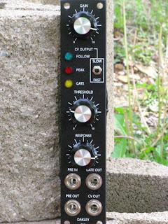
Oakleysound EFG, as assembled by Krisp1. Note that this panel layout is different from the 1U panel shown on the Oakley Web site.
What is an Envelope Follower?
So what is an envelope follower? Well, you know what an envelope generator is. It creates a signal whose (primary) purpose is to represent the volume of a sound over time; the signal is intended to be used as the control input to a VCA. An envelope follower, rather than creating an envelope from scratch, accepts an audio input and then outputs a control voltage that is proportional to the volume of the input audio at any given moment. The louder the volume of the input signal, the higher the control voltage output.
The Oakley EFG also contains a gate generator, that turns on when the input signal rises above a set level, and turns off when it drops below that level. For instance, as an alternative to having a VCA track the input level of your source, you could use an envelope generator connected to the VCA to re-shape the input signal's envelope. For this, you connect the EFG's gate generator output to the gate input of your envelope generator. The EFG's gate serves as an alternative to the normal gate signal that you would get from a keyboard connected to the synth.
EFG Features and Controls
An obvious application of an envelope follower is to make a VCA follow the envelope of some sound produced externally from the synth, such as the sound of a conventional instrument picked up from a microphone or electromagnetic pickup (e.g., electric guitar). These instruments and devices produce signal levels that are far lower than the signal levels used in a modular synth. Towards that end, the EFG incorporates a high-gain, high-impedance preamp, into which you can plug in a dynamic microphone, a self-powered condenser microphone, or an electric guitar/bass directly. The preamp has a very wide gain range, so that it can also accept line-level signals. It provides its output directly to the envelope follower's input; the preamp output is also available directly at a panel jack. A red "PEAK" LED on the panel indicates the onset of clipping in the preamp.
The envelope follower itself follows whatever signal is input to the preamp. A green "FOLLOW" LED on the panel lights up to indicate the control voltage being output; brighter indicates a higher voltage. This version of the EFG provides only one control for the envelope follower itself: a panel switch that selects slow or fast tracking. (Apparently the board can accommodate a pot that allows the envelope generator tracking speed to be varied.)
The gate generator outputs a gate signal that indicates the presence of a signal at the audio input. The gate is at 5V when a signal is present, and at ground when the signal is absent; this is pretty much the standard for modular gear. (It might or might not work with other synths; for instance, it won't work with Moog or Yamaha gear without conversion circuits.) The yellow "GATE" LED lights when the gate is active. The primary use of the gate is to control an envelope generator, in the same way that a keyboard gate does. You could then use the envelope generator to re-shape the audio signal. For instance, by setting your envelope to a fast attack, slow decay, and zero sustain level, you could make an instrument that sustains indefinitely (say, a saxophone or a violin) fade out like a piano.
The THRESHOLD control on the panel determines the level that the input signal has to reach in order to be considered "active". The RESPONSE control adds hysteresis to the threshold level; as you turn the control to the right, the turn-on level goes higher while the turn-off level goes lower. You can use this sort of like a noise gate. If your input signal is a source that fades out gradually, like a guitar or piano, you can set the control to a slow setting so that it the gate remains active for a time after the signal fades below the turn-on threshold. It helps prevent the gate from thrashing back and forth when the signal level is near the threshold. I found that when using an electric bass as the source, I had to set this to a high value to prevent the gate from chasing the waveform; in other words, turning on and off with each cycle of the waveform.
Using the EFG
I tried several things with the EFG. My first patch was to plug an electric bass into the EFG's audio input. I routed its audio output to an MOTM-190 VCA configured as a ring modulator, and fed the output of a VCO to the 190's other input. The output of the 190 went to a Dotcom Q109 VCA which served to actually control the level of the output signal.
I started by connecting the EFG's control voltage output to the Q109's control input. With this configuration, I could play the bass and have its output ring modulated against the VCO. The output from the Q109 tracked the envelope of the bass, so that notes played on the bass attacked and decayed the same as if I were playing directly through an amp. That worked well with the envelope follower tracking switch on SLOW; when I put it on FAST, the envelope generator chased the waveform somewhat. That was actually kind of interesting, but not what I was wanting at the moment.
Next, I plugged in an electric guitar. With the MOTM-190 still configured as a ring modulator, I unplugged the control voltage output from the Q109 VCA. I then plugged the EFG's gate output into a Q108 envelope generator, and plugged its output into the Q109. I was able to obtain steel-drum-like sounds by setting the envelope for minimum attack, short decay, and zero sustain. With a longer attack and high sustain level I could get things that sounded like radio interference, or detuned violins; it helps if you turn the RESPONSE control up so that the gate remains active long enough to reach the sustain phase. One thing that doesn't work is to set up for a long release and then mute notes on the guitar: no matter what you set the envelope generator release to, the VCA can't amplify a signal that isn't there! That's one thing you have to get used to when you use an instrument with an envelope follower.
I did find that it was rather difficult to set the THRESHOLD control to get the gate to behave exactly the way I wanted. With a moderate setting of the RESPONSE control, the threshold range between the point where the gate would go off too soon, and the point where it would stay on indefinitely due to noise picked up by the guitar, was pretty small -- between the 2 and 3 positions. Turning the gain up helps some, but then you get into clipping in the preamp section. If I were seriously going to use the guitar as an input to the EFG in a patch, I'd probably put a compressor in line ahead of the EFG.
Technical Details
The EFG circuitry consists of a single board, mounted at a right angle to the panel and secured to it via the three pots, in the style of most MOTM 1U width modules. The build quality is excellent; the soldering is very clean and the leads to the panel-mount components are nicely dressed. The board came equipped with the MOTM 4-pin power connector; there is also provision on the board to install a Dotcom power connector. A MOTM-style power cable, with latching connectors, was shipped with the module.

All ICs are socketed, for easy replacement if needed. The board has ferrite beads to clean up in the incoming power, and diodes to protect against the power cable being plugged in backwards. I couldn't figure out what brand the pots are, but the feel is smooth and I didn't notice any glitches when turning the knobs. The jacks are Switchcraft enclosed jacks, which are top-quality parts.
I did some tests to look at what kinds of voltages were coming out. For the envelope control voltage, with no input, the output is at zero volts, as you might suspect. I set up an input signal and varied the gain so that it was just below the point where the PEAK light comes on; at this level, the envelope follower outputs 6 volts. It will go higher, past 10V, if you let the input stage be overdriven, but of course at this level the preamp's audio out won't be very useable.
The gate outputs 7V when active, and I verified that it will gate an Encore Electronics universal event generator (a module that is known to be picky about its gates). With the gate THRSHOLD and RESPONSE controls set full counterclockwise, the gate threshold occurs at the point where the envelope follower is outputting about 1 volt.
The board has two unused features which could be exploited. There is a provision to add a lag control to the envelope follow control voltage. Also, by cutting a jumper, the preamp section can be separated from the input to the envelope follower and gate generator circuits, which would allow one to use the preamp for an instrument and then put its output through additional processing before inputting it to the follower.
Conclusion
To be honest, I had not previously considered buying any of the Oakley/Krisp1 modules solely because of the sucky (for Americans) dollar/pound exchange rate, which meant that a similar module from a North American source would nearly always cost significantly less. But when Krisp1 had their close-out sale on this module, I couldn't resist. I'm glad I made the purchase. This is going to be a very useful module, both for running conventional instruments through the modular, and for interfacing the modular to other synths. For instance, I could run the output of a polysynth into the EFG and use the control voltage output to control the cutoff of a VCF, adding an envelope-filter capability to the polysynth. Or, using the EFG in combination with a waveshaping circuit, I could make an approximation of a guitar synthesizer. My only comment is the small useable range of the gate THRESHOLD control. Other than that, it's a great module.
Sunday, April 17, 2011
Remove Before Flight: the making of a trance track
I've been wanting for a while to take a shot at an electronica track. I wanted to do it as a new challenge to myself -- I've listened to lots of electronica, but have not tried writing any before -- and as a way of putting some rhythm and melody back into my music. I've been doing a lot of atonal experimental stuff lately and I needed to get back in the groove, figuratively and literally. Here is the result, from my Web site.
The Web site writeup describes the who-did-what for this track, but I wanted to go a bit more into the decision-making process here. Remove Before Flight started out as a drum pattern. A very complicated, cluttered drum pattern. I started with a low tom (not a kick; more on that in a moment) hammering a 4/4, and added drum after drum until I had, well, a mess. Then I started taking stuff back out. I kept doing that until I had a recognizable pattern. The snare and cymbal play a bit while the tom keeps the beat pinned down. One thing I quickly recognized about it is that there is no obvious place for the "one" beat. When I put together the place where the first heavy pad sound comes in, I realized that I had started it on the wrong beat! I went with it, and there are several places in the track where "one" gets redefined, although it isn't glaringly obvious.
I had several specific things that I wanted to do with this track: (1) get the Kawai K5m involved; (2) build a modular patch involving the MOTM-510 WaveWarper; (3) experiment with Shepherd tones; and (4) put together an idea that I've had laying around for a while called the "drum console". The first two sounds that come in after the drum pattern starts -- the bass and electric-piano-like chords -- are both out of the K5m. I've done some stuff with the K5m before, but like a lot of people, I always found the additive synthesis method hard to get a feel for. However, after doing the Mississippi Statescape entirely with additive synthesis (albeit using the simpler Minky Starshine plug-in), I felt like I was ready to take another crack at it.
I started with a patch that I had built previously for part of Solar Flare. I tweaked on that, looking for an interesting melody patch, but it turned out to work better as a bass patch. Then I created another patch for the pulsing electric-piano-like sound. I recorded both of these as virtual tracks, so when I did the mixdown I had to put the K5m in multi mode, which I've never used before, and take the two patches out of separate outputs. And by doing that, I discovered something: the K5m is a lot quieter in multi mode! I'm not quite sure why this is; I think the K5m sums all five outputs together when it's in single mode. The K5m is known for being rather noisy; I've done the mod on mine to increase the output levels, but it's always tough to get the gain staging with it set up right. But from now on, whenever I record the K5m, I'm going to use the multi mode even if I'm only using it monotimbrally. (I found out something else interesting: in the multi mode, you can decide how many voices to allocate to each patch! I don't know of any other synth that lets you control the voice allocation in multitimbral operation this way.) Using poly mode 2 chops off the release phase of each note when the next note starts, giving more of a feel of a monosynth without using the 106's notoriously odd-sounding unison mode.
The high-pitched thing that sort of sounds like a pipe organ is from the JD990. Except for at the beginning, this is always layered with a big pad patch from the Matrix-1000. This turned out to be a good combination, with the somewhat shrill patch from the JD990 layered with the bassy and rather muddy Matrix-1000. I created the 990 patch specifically for this; the M1000 patch is one that I've had laying around. There are several things in the M1000 patch that are modulated by aftertouch to produce a somewhat unsettling detuning effect, which you can hear as the "chorus" portions of the track trail off into the quiet parts. It's a great demonstration of the M1000 modulation matrix.
The track actually uses three different bass patches. I started out with the K5m bass in the quiet parts, but I decided it was too up-front. I remember a patch that I had put together on the JD800 to emulate an electric bass. The basic patch is two layers; I had defined it with a third, disabled layer in an attempt to emulate an 8-string bass. That didn't really work out, but playing it way down at the far left end of the keyboard, it made a great near-subsonic bass for the quiet bits of this track. I knew that neither the K5m nor the JD800 basses would work as the sustained bass that I needed for the big choruses, so for that I created a third bass patch using the V-Synth. This patch has the ability to vary the low end harmonic content using the panel performance knobs (and corresponding MIDI CC #'s), which I use at the final chorus part. I mentioned using a low tom instead of a kick in the drum pattern. I did that because I knew I would be using a deep bass patch at some point in the track, and I don't like a kick drum cluttering up the bass spectrum. My observation is that when you do a track like this, you have to make a choice -- either use a deep kick and keep your bass patch in the mid-bass region, or use a deep bass and don't use a kick. Most electronica producers usually do the former, but I think I prefer the latter. (Must be my progressive-rock background coming through...)
I wanted a sequence that would capture the simplicity of a modular driven by an analog sequencer, but I didn't want to actually use an analog sequencer because (1) I didn't want the sequence to be quite that tick-tock, and (2) I don't have an analog sequencer. Having Metro drive the Juno 106 with a repeating pattern turned out to be just the thing. Funny thing about this: The sequence was one of the first things I did after putting together the drum pattern. I started it using a piano-like patch on the 106 as a placeholder, and I kept using that while I worked on other parts of the song. When the track was almost finished, I finally went back to it to create the patch I had intended, but nothing seemed to work quite as well as the piano patch, even though that patch wasn't what I had in mind and wasn't at all right for the track. I finally sort of compromised with myself by creating a patch that sort of sounds like what you'd get if you took a Wurlitzer and ran it through a wave shaper and an octave divider. This got me closer to what I wanted the sequence to sound like, without sounding too retro. The key to this patch was using gobs of the sub-oscillator, which has a different sound than the primary pulse waveform set to 50% duty cycle.
The Discombobulator plays a big part in Remove Before Flight. In the first quiet segment, there are a variety of sound effects produced using FM techniques. At the first of the year, I purchased three MOTM-310 micro VCOs from someone who was breaking up a large modular, with the specific intention of using them for FM patches. I set up a three-operator patch with one VCO modulating the second one, which modulates the third one. The first VCO is operating at a lower frequency and itself being modulated by an LFO. This patch uses triangle waves as the modulating waveforms; I've found that this often produces more interesting results than the sine waves used in the classic Yamaha FM synths. For this patch, no keyboard or other controller was used; I produced a track of about five minutes' worth of various sounds by tweaking the knobs. I recorded the audio in Metro and then chopped the track up into bits, about two minutes' worth of which actually made the final cut.
In the second quiet part, there's a series of atonal melodies. This was done using the MOTM-510 WaveWarper, which is sort of a super-duper ring modulator that takes three audio inputs and performs an analog computation on them. Two of the 310s were set to an interval (minor third, more or less) and sent to the X and W inputs of the 510. The third 310 was set to a lower frequency and modulated slightly by the low-frequency noise output of an MOTM-101. To play this, I used a keyboard interfaced via the MOTM-650 MIDI/CV interface. I configured a group of two channels and set the group to unison mode. An interesting feature of the unison mode is that if you play one note, both channels output that note. However, if you play two notes, the two channels split and each one takes one of the two notes. Each channel was fed to the control input of one of the 310 VCOs. By doing this, I could play the fixed interval that the 310s were tuned to by playing one note, or play another interval by playing two notes. Unlike the FM patch, this was not pre-recorded as an audio track; I recorded it as MIDI and played the track along with the other synths during the virtual mixdown.
The Discombobulator did one other function: That organ-like patch from the JD990 that I mentioned? It went through the Encore frequency shifter. I configured an aux output on the MOTM-650 to respond to mod wheel (MIDI CC #1) and used that control voltage to control the shift amount. The up-shift and down-shift outputs went to two channels of the mixer and were panned left and right for a stereo effect.
I did the Shepherd tones with Csound, as I have described in a previous post. I captured this as an AIFF file directly from Csound's output. This was imported into Metro and processed as described in the previous post.
The drum console is something that I'll say more about in a later post. One of my frustrations with conventional drum machines is that there is no easy way to change the pitch of the drums you select; for example, on the DR-202, you can change the pitch by going into the drum kit and changing it for that drum assignment in that kit, but it requires menu diving and is something you can't do at performance time. I've been wanting a way to play a particular drum sound over a range of pitches, to simulate e.g., roto-toms. So what I did is: I wrote a Csound program that loads a set of eight drum or percussion samples, and maps each one to a range of eight MIDI notes. Depending on the note played, it shifts the sample up or down, over a range of about half an octave. To play it, I use a Monome 40H, which has 64 keys in an 8x8 arrangement. Each row of the Monome corresponds to one sample; as you go from left to right on the row, it plays the sample at higher pitches.
Because the keys of the Monome aren't velocity sensitive, I coded the Csound program to take input from a Korg Nanocontrol to set a "velocity" parameter for each sample. Each of the 1 through 8 sliders on the Nanocontrol maps to one sample. When the slider is full up, the sample plays pretty much unaltered in dynamics. As you move the slider down, the attack time is increased; the volume is decreased, and a bit of low-pass filtering is applied. At low settings this actually produces a rather unrealistic attack sound, but I though it was interesting so I left it that way. Also, the rotary knob that goes with each channel is used by Csound to pan the sample.
I recorded the drum console parts as MIDI data from the Monome and Nanokontrol (which was tricky because I had to use the OSX IAC bus, and anytime you use the IAC bus you have to be very careful that you don't create a MIDI thru loop). So during the virtual mix I had this playing back through the Csound program. I routed the audio to its own output pair on the audio interface and to the mixer, where reverb got added. So, the resulting audio went from the digital domain to analog, and back to digital again. I learned a lot doing all this. It produces some interesting results, especially with the volume and attack manipulations. I want to extend this idea so I have a lot more control over various parameters and modifications of the samples. One other thing I learned is that the Monome isn't ideal as a drum pad controller; the buttons are kind of spongy and they have too much give for good drum pattern playing, in addition to not being velocity sensitive. But I don't know of any drum pad controller on the market that has 64 pads.
For the mixdown process, I had 12 MIDI tracks going on the various instruments, with everything being fed to the Mackie CR1604 mixer (of which I used all but one input channel, and all four of the effects returns). Nearly all of the mixing was pre-automated by setting up MIDI volume and pan commands to the various synths, so that once I had set the initial levels at the mixer, I didn't have to touch the faders during playback. There was a little bit of riding the master levels to avoid too much clipping -- I didn't use any compression. After that had been recorded to two-track in Metro, there were two additional (stereo) tracks that had to be mixed with the main two-track inside the box. One was the FM sounds from the Discombobulator, which had been chopped up from a longer track. The other was the Shepherd tones, which I wanted to keep in the digital domain, and anyway I had not set up the Shepherd program to be MIDI-controllable. That final in-the-box mix produced the track that you hear.
Remove Before Flight is Part I of the Flight Trilogy, all three of which will be electronica of some sort. I'm just starting to think about Part II. It will be called either "Sea of Crises" (a geographic feature on the Moon) or its Latin equivalent, "Mare Crisium". Right now I'm thinking it will be a downtempo piece, but I haven't decided that for sure.
Thursday, April 7, 2011

Saturday, March 12, 2011
Electricity for Synth-DIY'ers: Operational Amplifiers
Now that we've covered the basic semiconductors and passive components, let's begin covering what happens when you put a bunch of them together on a slab of silicon -- the integrated circuit. One of the most basic integrated circuits, used in both analog and digital systems, is the operational amplifier, or op amp for short. Op amps are one of the most useful ICs; they can be used to amplify or attenuate a signal to any extent desired, invert a signal, and solve signal buffering and impedence-matching problems. Further, they can be used to conveniently implement active filters in the audio range, do voltage level comparisons, and a host of other analog signal processing functions.


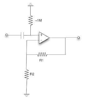

Basic Active Filter Circuits
Consider the following circuit:

Note the capacitor in the feedback path. What is this capacitor doing to the feedback? Well, start by considering a very low frequency: At a low enough frequency, the capacitor is essentially an open circuit, so only the R1 resistor in parallel with it has any effect. This reduces to your basic inverting amplifier with gain determined by the formula for an inverting amplifier: R1/R2. But what happens as the frequency goes up: The capacitor starts to let some current through, in addition to what goes through R1. In effect, the capacitor is reducing the value of R1 by allowing some current to bypass it. This gets more pronounced as the frequency goes up, until the frequency is reached where the capacitor has effectively shorted out R1. At this point, R1's effective resistance is zero, and the full amount of feedback is being applied to the inverting input, which cancels out the input signal at that frequency and reduces the op amp's gain at that frequency.
This circuit is a low-pass filter. It has a certain gain at low frequencies and less gain as the frequency goes up; at a sufficiently high frequency, its gain is zero. Doing the math, we find that, just like any filter, there is a cutoff frequency determined by the capacitor's value and above that value the gain rolls off at 6 dB/octave, making it a single-pole filter. The cutoff frequency is: 1/(6.2832R1C) where R1 is in ohms and C is in whole farads.

This circuit is a high pass filter. From the above discussion, you can probably already guess how it works. At low frequencies, the capacitor is essentially open, so full feedback is applied to the inverting input, and the op amp's gain is zero. As the frequency increases, C starts to conduct and at a high enough frequency it essentially becomes a straight wire. At that frequency, the circuit's gain then is determined by R1/R2. The formula for cutoff frequency is the same as for the low pass filter. Note that this circuit, unlike the low pass filter circuit, is non-inverting with respect to the input. Inverting and non-inverting configurations exist for both low pass and high pass filters.
What if you want more than a one-pole response? Well, an obvious answer is to put several of the above circuits in series. For instance, if you use two, you get a two-pole filter with a 12 dB/octave rolloff. However, using this method for multi-pole filters means using an op amp for each stage, which can make for an expensive circuit. So, electrical engineers have devised all kinds of devious circuits for implementing multi-pole filters that do not need an op amp for each pole. For instance, the Sallen-Key circuit often used in synth filters implements a two-pole low pass or high pass filter with only one op amp.

Here is something that people often get confused about when they read about op amp-based filter circuits. The topology is the logical arrangement of the components in the circuit. There are a bunch of ways of designing filter circuits, particularly multi-pole filter circuits. The Sallen-Key is one such topology; others often found in synths are the biquad and the multiple feedback. The response class refers to the general shape of the response curve. The three types you will hear most often in audio systems are Butterworth, Chebyshev, and Bessel; most synth filters belong to the Butterworth class. The differences between them are in exactly what the frequency response curve looks like; for instance, the Butterworth type is very flat in the passband, while the Chebyshev has some variations ("ripple"). All three of these filter types can be implemented in various topologies, and usually the difference is in the ratios between certain components. There is some pretty complicated math behind these, but you don't have to do the math; there are all kinds of design tools that allow you to plug in the desired characteristics and it will calculate the component values for you. Here is a simple one which will calculate a Sallen-Key (12 dB/octave) low-pass filter of the Butterworth class; all you have to put in is the desired cutoff frequency and one capacitor value. I'll do a future post which explains some of these active-filter types in more detail.
Compensation and Offset Nulling
All op amps require what is called compensation, in order to keep the op amp from going into self-oscillation under certain circuit conditions. The compensation consists of one or more capacitors that are placed into the op amp's internal circuitry. The first op amps were externally compensated -- they required the designer to add capacitors to compensation terminals on the device. However, most op amps today are internally compensated; the compensating capacitors are built into the op amp itself. In terms of ultimate performance, internally compensated op amps are a compromise; using external compensation allows the designer to extend the op amp's bandwidth and/or reduce its power draw, depending on the need. However, in designing synth circuits, these are seldom important factors. Therefore, there is usually no reason not to use internally compensated op amps in synth circuits.
The development of the operational amplifier actually precedes the advent of the integrated circuit. Op amps were first devised in the 1930s as a means of solving various amplification and impedence-matching problems in long line telephone circuits. At the time, they were obviously constructed using tubes since the transistor had not yet been invented; as the circuits were mass produced, they started being packaged into forms that allowed them to be treated as a single component -- some tube types were packaged such that the entire circuit could be plugged into a socket as if it were a single tube.

Philbrick Labs K2-W tube-based operational amplifier. Photo from Wikipedia Commons.
Much research in the pre-IC days went into miniaturizing these circuits, and making them work at lower voltages. A few op amps intended for high-end audio applications are still made as "bricks" implemented with discrete transistors, but nearly all other types are made as ICs these days. (An aside: One engineer who played a significant role in the development of the early solid-state op amps was a certain young Alan R. Pearlman, who would later play a much larger role in the development of the music synthesizer.)
The first monolithic IC op amps were developed by Fairchild in the early 1960s. They introduced the first one, the µA702, in 1963; it had some unfortunate characteristics and was not a success. However, in 1965 they followed this up with the µA709, which fixed the 702's problems and went on to see widespread use; it remained in production into the 1980s. Then things picked up; National Semiconductor challenged Fairchild by introducing its LM101/201/301 series in 1967. (The series of numbers represented different ambient operating temperature ranges, with the 3xx being the commercial series and the 1xx being mil-spec; this pattern continues today for most ICs designed by National.) Fairchild said "oh, yeah?" and the next year they introduced what would become the canonical op amp for decades: the µA741. The 741 was the first internally-compensated op amp (we'll get to compensation later). Variants of the 741 are still in production today.
If you are interested in reading a very good and detailed story of the development of the op amp, see this paper published by Analog Devices.
Opamp Basics
A basic opamp has two inputs and one output. The two inputs are known as the inverting and non-inverting inputs; as one might guess, the output will be inversely proportional to the signal at the inverting input, and directly proportional to the signal at the non-inverting input. That's a bit of an over-simplification, though; it often leads beginners to believe that what the opamp does is amplify the difference between the two inputs. There's more to how an opamp works than that, though.
Here, in three short rules, is what an opamp does (or tries to do):
- The opamp wants the voltage at its two inputs to be equal.
- It assumes that a feedback path exists between the output and the inverting input.
- It uses this assumption to vary the output to try to make the two inputs equal.
If no feedback path exists, the opamp will drive its output to its minimum or maximum voltage, which depends on the power supply voltages and the opamp's circuit design. (Some opamps will go "to the rails" and some will stop a volt or two short.) Thus, most useful opamp circuits include a negative feedback path. Another way of putting this is that without any feedback, the opamp has extremely high gain -- almost any non-zero inputs drive it to clipping, in one direction or the other. (The theoretical ideal opamp has infinite open-loop gain. Real opamps of course cannot go to infinity, but most types have open-loop gain factors within the audio range in the tens of thousands.) The feedback path is what controls this gain. From there, it follows that how much feedback is supplied can control the opamp to provide more or less gain, and this is exactly the case.
Symbology
We'll introduce the symbology at this point. The symbol for a basic opamp is:

The two pins show on the left are the two inputs: inverting (indicated by '-') and non-inverting (indicated by '+'). The pin on the right is the output. The power and ground pins are frequently not show, but when they are, they are show sticking out of the top and bottom; any other special-purpose inputs that the op amp has will also be shown at the top or bottom. In isolation, illustrators will usually draw the opamp symbol with the non-inverting input above the inverting input. However, in a schematic, the reverse is often true; conventionally the feedback path is drawn above the opamp symbol, and since it connects to the inverting input, to reduce the number of crossing paths the inverting input frequently gets placed on top. Some schematics will use the '+' symbol to indicate the non-inverting input and the '-' symbol to indicate the inverting. But others will use the pin numbers of the specific IC, in which case you need to know what kind of opamp it is and have access to the pinout. In this article, we will keep the non-inverting input on top throughout, to reduce confusion.
The Basic Amplifier Circuits
There are two basic configurations of amplifier circuits using an opamp, the inverting configuration and the non-inverting configuration. The inverting configuration has the effect of the output being the inverse of the input; with the non-inverting configuration, the output is identical to the input except for gain. Although the inverting configuration is used more, the non-inverting configuration is easier to understand and it does have its uses, so we'll introduce it first. It looks like this:

Note the resistor connected between the output and the inverting input. This is the feedback path. Thinking back to the three rules, picture what happens when a positive voltage comes to the opamp from the external circuitry. It raises the voltage at the non-inverting input. The opamp then wants the inverting input to rise to the same voltage as the non-inverting input. In order to accomplish this, it raises the voltage level at the output.
That voltage goes over to the inverting input, where some of it is bled off to ground by the other resistor. The two resistors form a voltage divider, so the voltage at the inverting input will be some fraction of the voltage at the output. Therefore, the output voltage will have to go up higher than the voltage present at the non-inverting input before the voltages at the two inputs become equal. For instance, if the two resistors have the same value, then they form a divide-by-2 divider, and the output will have to rise to twice the voltage that is present at the non-inverting input before the circuit settles.
All of this happens very fast. The speed at which the opamp is capable of responding to its input determines its maximum response frequency, or bandwidth. Nearly every opamp on the market today has a bandwidth that extends well beyond the audio range, so in an audio application, you will rarely have to worry about it; you can assume that everything happens instantaneously. (If you get into radio, or high-speed data circuits, that assumption is no longer valid.)
The ratio of the two resistors determines the gain of this circuit. The ratio in the middle of a two-resistor voltage divider is the total resistance divided by the resistance of the "bottom" resistor; in this case R2. So the gain of the non-inverting amplifier configuration is (R1+R2)/R2, or (R1/R2)+1. In the simplest case, where R1 is replaced by a straight wire (i.e., zero resistance) and R2 is omitted (infinite resistance), the result is a unity-gain amplifier; the output will be identical to the input. What good is a unity-gain amplifier? Well, one use is for re-driving signals that can't take being loaded down, such as signals from guitar pickups. Many opamps have extremely high input impedance, and a unity gain buffer is perfect for taking signals from high-impedance sources and repeating them with lower output impedance. Note one implication of the gain formula: in the non-inverting configuration, you can't achieve a gain of less than 1.
(By the way, in practical circuits, it's not a good idea to totally omit R2. Opamps often "bleed" a very small amount of current internally back into their inputs. If this bleed current doesn't have a path to ground, it can cause the opamp to go open loop and drive the output to the rail. If the need is for a unity-gain circuit, a 1M resistor can usually be used for R2 without any practical effect on the gain ratio, and it will allow the leakage currents to bleed off.)
The inverting amplifier configuration looks like this:

How does this one work? Per the three rules, when a positive voltage comes from the external circuit, it applies a positive voltage to the inverting input. Because it is the inverting input, the opamp will respond by pushing the output negative, in an attempt to counterbalance the positive voltage and bring it back to the voltage level of the non-inverting input, which is at 0V since it's grounded. The voltage level that the output has to go to in order to accomplish this depends on the ratio of the two resistors. Since the resistors directly determine the proportion of the input signal and the feedback that get combined at the inverting input, the gain equation for the inverting configuration is simply R1/R2. Unlike the non-inverting configuration, the inverting configuration can achieve a gain of less than 1; as you can see from the formula, as R2 gets large, the gain goes towards zero. Thus the inverting configuration can be both an amplifier and an attenuator.
So when do you choose one configuration over the other? Well, for one thing, the inverting configuration obviously inverts the signal, which is useful in its own right sometimes. More importantly, though, is that you will see below that most of the more sophisticated op amp circuits require an inverting configuration -- they don't work the other way. So why not just use the inverting configuration for everything? Well, for one thing, this may result in unintended inversion of the input, which will make you have to add an extra inverting stage to get the signal right side up.
However, a more important reason is in the fact that, in the inverting configuration, the two gain-setting resistors provide a "sneak path" around the op amp between the input and the output. This can cause a problem regarding the input impedance of the circuit. The op amp itself has incredibly high input impedance, which can be a very useful property (in, e.g., a preamp for a mic or guitar). However, if the op amp is driving something else with low input impedance, the path through the resistors will lower the effective input impedance. You could fix that by using high values for both resistors, since the ratio of the resistors and not the values per se is what determines the gain. However, past a certain point (when one of the resistors gets up past about 100K), you will start to have noise and voltage offset problems.
The non-inverting configuration does not have this problem because there is no connection between the input and the feedback path. So what you often see is that, for a given device, non-inverting circuits are often used for the external inputs and outputs, and most everything in between uses inverting circuits.
Stuff You Need to Know at This Point
Now that you understand the basic principles behind the opamp, before we proceed let's go over some of the requirements and practical limits of real opamps. Most opamps require both a positive and a negative power supply, depending on the type, and these must usually be of the same magnitude in order for the opamp to work properly. In other words, if the negative supply is -15V, a positive supply of +5V won't do; you need +15V. The power supply voltages limit how far the output can swing in either direction. They also limit what input voltages are permitted; with most opamp types, the inputs must be kept at least 1-2V away from the supply voltages. If the input limits are exceeded, the opamp may go into a condition called "latchup" where it no longer responds to its inputs. Latchup generally requires that the power be removed to reset the circuit, and it may harm the IC. If there is a possibility of the inputs exceeding the opamp's specified voltage, such as an opamp connected to an external input jack, it is a good idea to protect the inputs. Usually this is done with zener diodes. There are opamps which can accept input voltages all the way to the supply voltages; check the vendor catalogs if you need one of these.
There are some opamps made to work with single supply voltages. These are sometimes useful particularly in battery-powered applications. With these, the input voltages must be kept between the power supply voltage and ground, so if you want to feed in an AC signal, you will need to add DC offset to the input and then remove it from the output.
Most modern opamps are protected against having their outputs short-circuited; if you short the output to ground, nothing bad will happen. However, there is a limit to how much current the output can supply, so if you short it to ground, the output will go to zero and stay there until you remove the short. The output current limits are printed in the specifications. If you are building a circuit to drive a very long cable -- say, an output module for a modular that needs to drive to the house mixer 75 feet away -- an opamp will a high-current output capability will be useful.
One other thing to be aware of: All op amps "leak" very small amount bias currents that occur internally on the inputs. These small currents have to have a path out via the input pins. Here's something to watch out for:

Note the capacitor on the non-inverting input; this would be typical if it was desired to block DC voltages from reaching the input. The problem is: those micro-leakages at the input are "trapped" by the capacitor; they don't have a path out of the circuit! The result is that the circuit will never reach equilibrium and the output will probably go to the minimum or maximum voltage and stay there. Here's how you fix that:

The extra resistor allows the leakage currents to bleed to ground. A 1M resistor will usually be large enough to not have any effect on the input signal.
Analog Arithmetic with Opamps
A frequent problem in synth circuits is the need to add or subtract control voltages. For instance, the control voltage fed to a VCO might need to be the sum of control voltages from the keyboard, the pitch wheel, and an LFO. Here is a circuit that will sum up any number of control voltages:

You can add any number of inputs to the input ladder at the left. To keep things simple, all of the Rx resistors should be of the same value; if you do so, the gain is Ry/Rx. Use Rx values of at least 1K to prevent the input signals from trying to back-drive each other. Note that, because this is based on the inverting-amplifier configuration, the output will be the negative of the sum of the inputs. That's easy to fix; just run it through a second inverting amplifier, with the gain configured as needed. Note that this circuit can also be used as an audio mixer; after all, a mixer is really just an adder. The one thing you might want to do if it is being used for audio mixing is add a DC-blocking capacitor (10 uF or so, non-polarized electrolytic) in series with each input.
You can subtract signals using the configuration above, preceded by an inverting amp that inverts the signal to be subtracted. However, here's a one-op-amp solution for computing the difference of two signals:

Note that this circuit is identical to what is commonly called a "difference amplifier" or "differential amplifier" (the latter is not-so-good terminology, but lots of people use it). The "balanced line" signal connection often used in recording studios consists of two signals, one of which is the negative of the other. You see this commonly in equipment such as microphones which use the 3-pin "Cannon" plugs and jacks; two of the pins carry the signals and the third is connected to the cable shield. You can use the difference amplifier circuit to convert this to a single-wire signal that you can process inside a piece of equipment. The difference amplifier produces an output which is proportional to the difference between its inputs. An interesting implication of this is that if both signals change by the same amount, the output does not change at all, because the difference between the signals didn't change. In the studio environment, this is called "common mode rejection" and is a big help in reducing noise pickup. The basic circuit should have R1 = R3 and R2 = R4; assuming so, then the gain is equal to R1/R2.
(Note that this is not the optimum version of this circuit; the main problem is that it's difficult to make the impedances of the two sides match exactly, which limits the circuit's accuracy. Here is an improved version, if you have a need for it.)
Differentiators and Integrators
Here's a pair of circuits that can be very useful particularly in a modular synth. The first is called a differentiator (not to be confused with a difference amplifier). What it does is produce an output which is proportional to the rate at which the input is changing; you can think of it as sort of a speedometer for the input signal. If the input is increasing, the output will be a positive voltage; if the input is decreasing, the output is negative, and if the input is not changing, the output is zero.

The gain of this circuit is proportional to the frequency of the signal fed into it, but is influenced by the values of R and C. The output voltage Vo = -RC(dV/dt), where R is the resistor value in ohms, C is the capacitor value in farads (not microfarads or nanofarads, but whole farads), and dV/dt is the rate at which the input voltage is rising or falling, in volts per second. (Don't worry about what the individual parts of the dV/dt stand for; just accept that it stands for "change in voltage with respect to time".) Note the minus sign, which is a result of this being an inverting-amp configuration. An easy way to think about this circuit is to assume an R of 1M and a C of 1 uF; this way the product of RC is 1, and then if the input is rising at 1V per second, the output is -1V as long as the input keeps changing.
The integrator is, mathematically, the opposite of the differentiator. To continue with the car analogy, you can think of the input as an accelerator for the output. When the input is positive, the output rises; its rate of rise is determined by the magnitude of the input. Same goes for a negative input; the output goes lower in proportion to the input. When the input is zero, the output remains where it was. Given that an input that remains positive or negative for any length of time will push the output to its power-supply-determined limit, it's useful to have a reset capability. This is shown in the schematic as a switch, but it would be a simple matter to substitute an NPN transistor or a mini relay so it could take a reset trigger signal.

Basic Active Filter Circuits
Consider the following circuit:

Note the capacitor in the feedback path. What is this capacitor doing to the feedback? Well, start by considering a very low frequency: At a low enough frequency, the capacitor is essentially an open circuit, so only the R1 resistor in parallel with it has any effect. This reduces to your basic inverting amplifier with gain determined by the formula for an inverting amplifier: R1/R2. But what happens as the frequency goes up: The capacitor starts to let some current through, in addition to what goes through R1. In effect, the capacitor is reducing the value of R1 by allowing some current to bypass it. This gets more pronounced as the frequency goes up, until the frequency is reached where the capacitor has effectively shorted out R1. At this point, R1's effective resistance is zero, and the full amount of feedback is being applied to the inverting input, which cancels out the input signal at that frequency and reduces the op amp's gain at that frequency.
This circuit is a low-pass filter. It has a certain gain at low frequencies and less gain as the frequency goes up; at a sufficiently high frequency, its gain is zero. Doing the math, we find that, just like any filter, there is a cutoff frequency determined by the capacitor's value and above that value the gain rolls off at 6 dB/octave, making it a single-pole filter. The cutoff frequency is: 1/(6.2832R1C) where R1 is in ohms and C is in whole farads.

This circuit is a high pass filter. From the above discussion, you can probably already guess how it works. At low frequencies, the capacitor is essentially open, so full feedback is applied to the inverting input, and the op amp's gain is zero. As the frequency increases, C starts to conduct and at a high enough frequency it essentially becomes a straight wire. At that frequency, the circuit's gain then is determined by R1/R2. The formula for cutoff frequency is the same as for the low pass filter. Note that this circuit, unlike the low pass filter circuit, is non-inverting with respect to the input. Inverting and non-inverting configurations exist for both low pass and high pass filters.
What if you want more than a one-pole response? Well, an obvious answer is to put several of the above circuits in series. For instance, if you use two, you get a two-pole filter with a 12 dB/octave rolloff. However, using this method for multi-pole filters means using an op amp for each stage, which can make for an expensive circuit. So, electrical engineers have devised all kinds of devious circuits for implementing multi-pole filters that do not need an op amp for each pole. For instance, the Sallen-Key circuit often used in synth filters implements a two-pole low pass or high pass filter with only one op amp.
Op Amp Filter Topologies and Response Types
Here is something that people often get confused about when they read about op amp-based filter circuits. The topology is the logical arrangement of the components in the circuit. There are a bunch of ways of designing filter circuits, particularly multi-pole filter circuits. The Sallen-Key is one such topology; others often found in synths are the biquad and the multiple feedback. The response class refers to the general shape of the response curve. The three types you will hear most often in audio systems are Butterworth, Chebyshev, and Bessel; most synth filters belong to the Butterworth class. The differences between them are in exactly what the frequency response curve looks like; for instance, the Butterworth type is very flat in the passband, while the Chebyshev has some variations ("ripple"). All three of these filter types can be implemented in various topologies, and usually the difference is in the ratios between certain components. There is some pretty complicated math behind these, but you don't have to do the math; there are all kinds of design tools that allow you to plug in the desired characteristics and it will calculate the component values for you. Here is a simple one which will calculate a Sallen-Key (12 dB/octave) low-pass filter of the Butterworth class; all you have to put in is the desired cutoff frequency and one capacitor value. I'll do a future post which explains some of these active-filter types in more detail.
Compensation and Offset Nulling
All op amps require what is called compensation, in order to keep the op amp from going into self-oscillation under certain circuit conditions. The compensation consists of one or more capacitors that are placed into the op amp's internal circuitry. The first op amps were externally compensated -- they required the designer to add capacitors to compensation terminals on the device. However, most op amps today are internally compensated; the compensating capacitors are built into the op amp itself. In terms of ultimate performance, internally compensated op amps are a compromise; using external compensation allows the designer to extend the op amp's bandwidth and/or reduce its power draw, depending on the need. However, in designing synth circuits, these are seldom important factors. Therefore, there is usually no reason not to use internally compensated op amps in synth circuits.
The ideal op amp should, if both of its inputs are grounded, drive its output to exactly 0V. Real op amps will usually have an offset ranging from microvolts to a few millivolts, depending on how the inputs are configured. This is caused by small current leakages in or out of the input pins. Some op amps have inputs to which you can connect a trimmer pot that you can adjust to null out the offset. This can be important in, for instance, a control voltage input to a VCO. If you need this, look for an op amp type that has "balance" or "offset null" inputs.
Op Amp Types and Specifications
These days, nearly all op amps are packaged in the familiar dual-in-line plastic package, in either through-hole or surface mount configuration. (A very few of the oldest types are still available in the metal can that looks like an oversize transistor with more legs.) A single part often contains more than one actual op amp; dual, triple, and quad packages are common. Single types nearly always have 8 pins while types containing more than one per package may have up to 16 pins.
Things that you (maybe) need to be concerned about when you are searching for an op amp for a synth application are:
- Number of individual op amps in the package
- Minimum and maximum power supply voltages
- Input impedances
- The gain-bandwidth product
- Whether the op amp can run off of a single supply voltage
- The voltage range of the output
- Output drive capacity
Subscribe to:
Posts (Atom)