- One commenter thinks that the TI may be the end of the Virus line, it having evolved far from the original Virus A design. What might Access (which has made its name in VA synthesis) follow it up with? I wonder if DSP design has progressed to the point where they could build a new VA that does synthesis by running actual circuit simulations in real time (something that has been speculated on in the Synth-DIY mailing list), and bring it in at a reasonable price point.
- I tend to agree with the posters who can't figure out why the Nord Wave is so pricey. I had thought from the name that it was a follow-on design to the famous PPG Wave keyboards, but it appears that it isn't quite that.

Tuesday, August 19, 2008
V/Wave/TI Review on VSE Forum
The poster "23" has written a fine comparative review of the V-Synth, the Access Virus TI, and the Nord Wave, on the Vintage Synth Explorer's forum (which, BTW, has a snazzy new format). The review lays out the advantages and disadvantages of each, bearing in mind that they aren't really targeted towards the same audiences. There are also some good responses in the comments, of which two salient points:


Tuesday, August 12, 2008
Whitney's pendulum waveform generator
In my August 8 post on the John Whitney Music Box, I mentioned a opto-mechanical device that Whitney used in the 1930s to generate waveforms which were imprinted on the optical soundtrack of some of his early experimental films. It is described, in the sources I've found, as consisting of 20 pendulums (presumably all swinging at different rates) connected in some fashion to an aperture or series of apertures which controlled light passing through to expose the film sound track. I mentioned in the post that I wanted to write a simulation of this, if I could figure out how it worked.
Since I was unable to find any further information, I made some guesses. My most significant guess is that the device was probably mechanically fairly simple. It would have had the ability to have additional pendulums added or subtracted (Whitney probably experiemented with it to come up with 20 as the optimum number for his purposes), which would seem to preclude any arrangement where all of the pendulums were linked to a single aperture -- it would be too difficult to add or remove pendulums. It probably had no power source other than the pendulums being hand started; since the experimental films in question were quite short, there was no need for the pendulums to run for hours or days on end. We know the pendulums cycled at sub-audio rates because the descriptions mentioned advancing the film very slowly during the imprinting process, so that the sound track would be shifted up into the audio range when the film was projected at normal speed. Also, that's reasonable considering that the fastest-beating pendulums found in mechanical clocks of the day cycled at about 3 Hz, and these were pendulums only a few inches long. (Most clocks had slower pendulums, because the larger mass and higher momentum kept better time and was easier to regulate; our old grandfather clock at home has a pendulum that takes about four seconds to complete one cycle.)
So my guess for the construction of the mechanism is something like this:

20 pendulums in a column file, front to back, with a light path running through them. Each pendulum has a shutter attached to its arm that blocks half of the path with the pendulum at rest; at one extreme the path is full open, and at the other the path is fully blocked. In an idealized form, one can see that the amount of light allowed through by any one pendulum is described by a sine wave (or more specifically, a cosine wave, assuming that all of the pendulums are started by being released from the full-open end of the swing). The light source is placed at one end of the file, and the camera which records the optical soundtrack at the other end. The pendulums all have different effective lengths, and will swing at different rates when released.
One big decision that I had to think about was the light source. Was it a simple light bulb, acting as a point source, or was it a focused beam? Not being able to decide, I resolved to try it both ways. With the setup I described above, it makes a considerable difference. Consider: A point source of light (this is true for sound too) can be visualized as a bunch of rays shooting out in all directions from the source. No two of the rays are parallel; there is always an angle (no matter how slight) between any two, and as you move further away from the source, the rays will spread further apart. If you place any solid obstacle with a cutout opening in front of the point souce, the rays that pass through the opening it will continue to spread out, and so at a sufficient distance, the opening will in turn look like a point source, just weaker. Another obstacle with an opening placed in front of that will, in turn, look like a still weaker point source. This is true even if the obstacles aren't all in a perfect line; some light will still get through. And the effect is enhanced if the light is contained by a reflective tube in between the obstacles.
A beam source behaves differently. In a focused beam, all of the rays (in theory) are parallel; there is no spreading. An obstacle placed in the beam, with an opening that is outside of the beam, will admit no light through. An obstacle with an opening that is in the beam will let some portion of the light through, in a shape that is described by the intersection of the shape of the beam and the shape of the obstacle. If a subsequent obstacle blocks out this part of the beam, then no light will get through at all even though the second obstacle might have an opening elsewhere. Only the light rays that have a straight path through all of the openings can pass. If no such path exists, no light gets through. (Ignoring edge diffraction effects.)
I decided to simulate the second case first. In doing so, in order to simply the math, I made one further assumption: that all of the pendulums had their shutters on the same side, and in the same shape. That is, there would be no case where one pendulum was blocking the left half of the beam and the other pendulum was blocking the right half; a "less closed" shutter would always pass all of the light admitted by any preceding "more closed" shutter. Doing so made the computation of the amount of light passed by all of the pendulums easy; it is simply the least amount of light passed by any individual pendulum, or:
min(pendulum1, pendulum2,pendulum3,...)
I simulated the motion of all of the pendulums as simple sine waves, ignoring nasty real-world unpleasantries such as friction, diffraction, unintentional coupling, etc. I ignored the bit about running all of the pendulums at subsonic rates and speeding them up; I reasoned that in the digital domain, that would have exactly the same result as running the pendulums at higher rates to begin with, so why bother? Instead, I just ran them at audio rates (or nearly) to start with. I figure that the difference in speeds between the slowest and fastest pendulums could not have been huge; probably the slowest pendulum would have cycled once per 5 seconds, and the fastest one at 3-4 Hz at most. And most likely the recording speed was no more than 1:20 of the playback speed; much slower and they would have run into problems with getting a reasonably linear exposure on the film (what the photographers call "reciprocity failure").
I wrote up the sim in Csound and ran it with six different sets of parameters for the pendulum rates. The audio result is here (it is an uncompressed AIFF file, 16-bit, 44.1, mono). There are six different sound samples in the file, each five seconds long, with a short amount of silence in between. The parameters for each sample are:
Sample 1:

Sample 4 (note the long-period amplitude variation):

Sample 5 (note the mirror-image symmetry of all of the pairs of spikes):

Sample 6 (again, note the mirror-image symmetry):

(I was mildly amused to note, when I imported the files, that all of the waveforms are inverted. I don't know if Csound generated them that way, or if they got that way somehow in the process of importing them into Metro so I could look at the graphs.)
For the second run, I change the simulation from a beam-source light to a point source. In this simulation, each pendulum shutter cuts off a certain percentage of the light, the next one cuts off a percentage of the light that passed through the first one, and so on. If all of the percent-open values are expressed in the range 0-1, as they are in the sim, then the computation becomes:
pendulum1 * pendulum2 * pendulum3 * ...
It's interesting to note that the communativity of multiplication implies that the order of the pendulums does not matter. That seems counterintuitive somehow, yet the math demands that it must be the case. In any case, the results weren't nearly as interesting. I ran it with the same set of parameters as for the first run. Here is the audio file. Nearly all of them came out looking and sounding like the graph below, which is from sample 6:

I'm not sure why these seem so much "orderly" than the samples in the first run; I had halfway expected the opposite. Still interesting, but not quite as much as the first set. Either, though, would have been an absolutely startling thing to hear coming out of a movie projector in 1938! Keep in mind as you listen to these that only a handful of people in the world had been exposed to any kind of electronic music at this point in history.
I plan to do some more work on this. One thing I want to explore: adding friction to the pendulums, in some fashion, to make them "run down". Currently, the pendulums have perpetual motion; they cycle at the exact same amplitude indefinitely. Recall from your high school physics that a pendulum's period depends only on its center of mass; as it loses energy, the cycle rate remains the same, with only the amplitude -- how far it swings to the sides -- decreasing. Having them all run down together, at the same rate per unit of real time, probably wouldn't be very interesting; the overall amplitude would just decrease. However, real pendulums won't do that anway. They will run down according to the number of cycles they have made, or the (angular) distance they have traveled, which means that faster ones run down sooner than slower ones. I want to add that to the sim and see what I get.
I also want to play with some different shutter sizes and shapes. For example, the shutter could be constructed such that the light is totally blocked at the center and open at either end of the swing. Or, it could be cut such that the pattern of variation as the pendulum swings is something other than a sine wave.
Below is the source code for the Csound orchestra (the .orc file). Instrument 101 was used to produce the first run, and Instrument 102 was used to produce the second run. Watch out for line wrap.
Since I was unable to find any further information, I made some guesses. My most significant guess is that the device was probably mechanically fairly simple. It would have had the ability to have additional pendulums added or subtracted (Whitney probably experiemented with it to come up with 20 as the optimum number for his purposes), which would seem to preclude any arrangement where all of the pendulums were linked to a single aperture -- it would be too difficult to add or remove pendulums. It probably had no power source other than the pendulums being hand started; since the experimental films in question were quite short, there was no need for the pendulums to run for hours or days on end. We know the pendulums cycled at sub-audio rates because the descriptions mentioned advancing the film very slowly during the imprinting process, so that the sound track would be shifted up into the audio range when the film was projected at normal speed. Also, that's reasonable considering that the fastest-beating pendulums found in mechanical clocks of the day cycled at about 3 Hz, and these were pendulums only a few inches long. (Most clocks had slower pendulums, because the larger mass and higher momentum kept better time and was easier to regulate; our old grandfather clock at home has a pendulum that takes about four seconds to complete one cycle.)
So my guess for the construction of the mechanism is something like this:
20 pendulums in a column file, front to back, with a light path running through them. Each pendulum has a shutter attached to its arm that blocks half of the path with the pendulum at rest; at one extreme the path is full open, and at the other the path is fully blocked. In an idealized form, one can see that the amount of light allowed through by any one pendulum is described by a sine wave (or more specifically, a cosine wave, assuming that all of the pendulums are started by being released from the full-open end of the swing). The light source is placed at one end of the file, and the camera which records the optical soundtrack at the other end. The pendulums all have different effective lengths, and will swing at different rates when released.
One big decision that I had to think about was the light source. Was it a simple light bulb, acting as a point source, or was it a focused beam? Not being able to decide, I resolved to try it both ways. With the setup I described above, it makes a considerable difference. Consider: A point source of light (this is true for sound too) can be visualized as a bunch of rays shooting out in all directions from the source. No two of the rays are parallel; there is always an angle (no matter how slight) between any two, and as you move further away from the source, the rays will spread further apart. If you place any solid obstacle with a cutout opening in front of the point souce, the rays that pass through the opening it will continue to spread out, and so at a sufficient distance, the opening will in turn look like a point source, just weaker. Another obstacle with an opening placed in front of that will, in turn, look like a still weaker point source. This is true even if the obstacles aren't all in a perfect line; some light will still get through. And the effect is enhanced if the light is contained by a reflective tube in between the obstacles.
A beam source behaves differently. In a focused beam, all of the rays (in theory) are parallel; there is no spreading. An obstacle placed in the beam, with an opening that is outside of the beam, will admit no light through. An obstacle with an opening that is in the beam will let some portion of the light through, in a shape that is described by the intersection of the shape of the beam and the shape of the obstacle. If a subsequent obstacle blocks out this part of the beam, then no light will get through at all even though the second obstacle might have an opening elsewhere. Only the light rays that have a straight path through all of the openings can pass. If no such path exists, no light gets through. (Ignoring edge diffraction effects.)
I decided to simulate the second case first. In doing so, in order to simply the math, I made one further assumption: that all of the pendulums had their shutters on the same side, and in the same shape. That is, there would be no case where one pendulum was blocking the left half of the beam and the other pendulum was blocking the right half; a "less closed" shutter would always pass all of the light admitted by any preceding "more closed" shutter. Doing so made the computation of the amount of light passed by all of the pendulums easy; it is simply the least amount of light passed by any individual pendulum, or:
min(pendulum1, pendulum2,pendulum3,...)
I simulated the motion of all of the pendulums as simple sine waves, ignoring nasty real-world unpleasantries such as friction, diffraction, unintentional coupling, etc. I ignored the bit about running all of the pendulums at subsonic rates and speeding them up; I reasoned that in the digital domain, that would have exactly the same result as running the pendulums at higher rates to begin with, so why bother? Instead, I just ran them at audio rates (or nearly) to start with. I figure that the difference in speeds between the slowest and fastest pendulums could not have been huge; probably the slowest pendulum would have cycled once per 5 seconds, and the fastest one at 3-4 Hz at most. And most likely the recording speed was no more than 1:20 of the playback speed; much slower and they would have run into problems with getting a reasonably linear exposure on the film (what the photographers call "reciprocity failure").
I wrote up the sim in Csound and ran it with six different sets of parameters for the pendulum rates. The audio result is here (it is an uncompressed AIFF file, 16-bit, 44.1, mono). There are six different sound samples in the file, each five seconds long, with a short amount of silence in between. The parameters for each sample are:
- Slowest pendulum at 10 Hz, with each additional one 10 Hz higher (20 Hz, 30 Hz, etc.).
- Slowest pendulum at 20 Hz, with each additional one 20 Hz higher.
- Slowest pendulum at 50 Hz, with each additional one 50 Hz higher.
- Slowest pendulum at 1 Hz, with each additional one 13 Hz higher.
- Slowest pendulum at 8 Hz, with each additional one 5 Hz higher.
- Slowest pendulum at 200 Hz, with each additional one 6.33 Hz higher.
Sample 1:

Sample 4 (note the long-period amplitude variation):

Sample 5 (note the mirror-image symmetry of all of the pairs of spikes):

Sample 6 (again, note the mirror-image symmetry):

(I was mildly amused to note, when I imported the files, that all of the waveforms are inverted. I don't know if Csound generated them that way, or if they got that way somehow in the process of importing them into Metro so I could look at the graphs.)
For the second run, I change the simulation from a beam-source light to a point source. In this simulation, each pendulum shutter cuts off a certain percentage of the light, the next one cuts off a percentage of the light that passed through the first one, and so on. If all of the percent-open values are expressed in the range 0-1, as they are in the sim, then the computation becomes:
pendulum1 * pendulum2 * pendulum3 * ...
It's interesting to note that the communativity of multiplication implies that the order of the pendulums does not matter. That seems counterintuitive somehow, yet the math demands that it must be the case. In any case, the results weren't nearly as interesting. I ran it with the same set of parameters as for the first run. Here is the audio file. Nearly all of them came out looking and sounding like the graph below, which is from sample 6:

I'm not sure why these seem so much "orderly" than the samples in the first run; I had halfway expected the opposite. Still interesting, but not quite as much as the first set. Either, though, would have been an absolutely startling thing to hear coming out of a movie projector in 1938! Keep in mind as you listen to these that only a handful of people in the world had been exposed to any kind of electronic music at this point in history.
I plan to do some more work on this. One thing I want to explore: adding friction to the pendulums, in some fashion, to make them "run down". Currently, the pendulums have perpetual motion; they cycle at the exact same amplitude indefinitely. Recall from your high school physics that a pendulum's period depends only on its center of mass; as it loses energy, the cycle rate remains the same, with only the amplitude -- how far it swings to the sides -- decreasing. Having them all run down together, at the same rate per unit of real time, probably wouldn't be very interesting; the overall amplitude would just decrease. However, real pendulums won't do that anway. They will run down according to the number of cycles they have made, or the (angular) distance they have traveled, which means that faster ones run down sooner than slower ones. I want to add that to the sim and see what I get.
I also want to play with some different shutter sizes and shapes. For example, the shutter could be constructed such that the light is totally blocked at the center and open at either end of the swing. Or, it could be cut such that the pattern of variation as the pendulum swings is something other than a sine wave.
Below is the source code for the Csound orchestra (the .orc file). Instrument 101 was used to produce the first run, and Instrument 102 was used to produce the second run. Watch out for line wrap.
; Simulates pendulums with individual aperatures, beam light source
; Assumes aperature is full open with pendulum at 0 deg, full close at 180 deg

instr 101

; Assign initial parameters
ifreq = p4 ; Base frequency
iinc = p5 ; Frequency increment
iscale = p6 ; Output scaling, 0-1
; Table names
itsine = 1


; Compute the phase for each of the pendulums
aph1 phasor ifreq
aph2 phasor ifreq+iinc
aph3 phasor ifreq+(iinc*2)
aph4 phasor ifreq+(iinc*3)
aph5 phasor ifreq+(iinc*4)
aph6 phasor ifreq+(iinc*5)
aph7 phasor ifreq+(iinc*6)
aph8 phasor ifreq+(iinc*7)
aph9 phasor ifreq+(iinc*8)
aph10 phasor ifreq+(iinc*9)
aph11 phasor ifreq+(iinc*10)
aph12 phasor ifreq+(iinc*11)
aph13 phasor ifreq+(iinc*12)
aph14 phasor ifreq+(iinc*13)
aph15 phasor ifreq+(iinc*14)
aph16 phasor ifreq+(iinc*15)
aph17 phasor ifreq+(iinc*16)
aph18 phasor ifreq+(iinc*17)
aph19 phasor ifreq+(iinc*18)
aph20 phasor ifreq+(iinc*19)

; Extract the waveform samples
asine1 tablei aph1, itsine, 1, 0, 1
asine2 tablei aph2, itsine, 1, 0, 1
asine3 tablei aph3, itsine, 1, 0, 1
asine4 tablei aph4, itsine, 1, 0, 1
asine5 tablei aph5, itsine, 1, 0, 1
asine6 tablei aph6, itsine, 1, 0, 1
asine7 tablei aph7, itsine, 1, 0, 1
asine8 tablei aph8, itsine, 1, 0, 1
asine9 tablei aph9, itsine, 1, 0, 1
asine10 tablei aph10, itsine, 1, 0, 1
asine11 tablei aph11, itsine, 1, 0, 1
asine12 tablei aph12, itsine, 1, 0, 1
asine13 tablei aph13, itsine, 1, 0, 1
asine14 tablei aph14, itsine, 1, 0, 1
asine15 tablei aph15, itsine, 1, 0, 1
asine16 tablei aph16, itsine, 1, 0, 1
asine17 tablei aph17, itsine, 1, 0, 1
asine18 tablei aph18, itsine, 1, 0, 1
asine19 tablei aph19, itsine, 1, 0, 1
asine20 tablei aph20, itsine, 1, 0, 1


; Do the min function on all the samples
aout min asine1, asine2, asine3, asine4, asine5, asine6, asine7, asine8, asine9, asine10, asine11, asine12, asine13, asine14, asine15, asine16, asine17, asine18, asine19, asine20

; Output
aout = aout*iscale*20000
out aout
; display aout, .01
endin
; Same as above except the light source is a point source.
; Assumes aperature is full open with pendulum at 0 deg, full close at 180 deg

instr 102

; Assign initial parameters
ifreq = p4 ; Base frequency
iinc = p5 ; Frequency increment
iscale = p6 ; Output scaling, 0-1
; Table names
itsine = 1


; Compute the phase for each of the pendulums
aph1 phasor ifreq
aph2 phasor ifreq+iinc
aph3 phasor ifreq+(iinc*2)
aph4 phasor ifreq+(iinc*3)
aph5 phasor ifreq+(iinc*4)
aph6 phasor ifreq+(iinc*5)
aph7 phasor ifreq+(iinc*6)
aph8 phasor ifreq+(iinc*7)
aph9 phasor ifreq+(iinc*8)
aph10 phasor ifreq+(iinc*9)
aph11 phasor ifreq+(iinc*10)
aph12 phasor ifreq+(iinc*11)
aph13 phasor ifreq+(iinc*12)
aph14 phasor ifreq+(iinc*13)
aph15 phasor ifreq+(iinc*14)
aph16 phasor ifreq+(iinc*15)
aph17 phasor ifreq+(iinc*16)
aph18 phasor ifreq+(iinc*17)
aph19 phasor ifreq+(iinc*18)
aph20 phasor ifreq+(iinc*19)

; Extract the waveform samples
asine1 tablei aph1, itsine, 1, 0, 1
asine2 tablei aph2, itsine, 1, 0, 1
asine3 tablei aph3, itsine, 1, 0, 1
asine4 tablei aph4, itsine, 1, 0, 1
asine5 tablei aph5, itsine, 1, 0, 1
asine6 tablei aph6, itsine, 1, 0, 1
asine7 tablei aph7, itsine, 1, 0, 1
asine8 tablei aph8, itsine, 1, 0, 1
asine9 tablei aph9, itsine, 1, 0, 1
asine10 tablei aph10, itsine, 1, 0, 1
asine11 tablei aph11, itsine, 1, 0, 1
asine12 tablei aph12, itsine, 1, 0, 1
asine13 tablei aph13, itsine, 1, 0, 1
asine14 tablei aph14, itsine, 1, 0, 1
asine15 tablei aph15, itsine, 1, 0, 1
asine16 tablei aph16, itsine, 1, 0, 1
asine17 tablei aph17, itsine, 1, 0, 1
asine18 tablei aph18, itsine, 1, 0, 1
asine19 tablei aph19, itsine, 1, 0, 1
asine20 tablei aph20, itsine, 1, 0, 1


; Do the min function on all the samples
aout = asine1*asine2*asine3*asine4*asine5*asine6*asine7*asine8*asine9*asine10*asine11*asine12*asine13*asine14*asine15*asine16*asine17*asine18*asine19*asine20

; Output
aout = aout*iscale*20000
out aout
display aout, .01
endin
Below is the score file (the .sco file). It is set up for the second run; to change it to do the first run, change all of the instrument numbers from 102 to 101.
; Function tables
; Cosine
f 1 0 16385 9 1 1 90

; base incr ampl
; inst start duration freq ment
i 102 0 5 10 10 1
i 102 5.5 5 20 20 1
i 102 11 5 50 50 0.8
i 102 16.5 5 1 13 1
i 102 22 5 8 5 1
i 102 27.5 5 200 6.33 1
Friday, August 8, 2008
The John Whitney Music Box
John Whitney is best known as a pioneer in experimental film and computer graphics, but he also did some work in experimental sound and sound synthesis. Jim Bumgardner has written a fun toy based on one of Whitney's ideas called the John Whitney Music Box, a screen shot of which is presented below:

Each of the little dots revolves in its own orbit. The period of any given orbit is exactly half of the period of the orbit outside of it. Whenever a dot crosses the positive X-axis, it triggers a synthesized sound at a certain pitch. The revolving pattern produces a fascinating patterns of sounds, repeating about once every five minutes, as the dots orbit about. There are 20 variations, with sounds ranging from plucked strings to chimes to sine-wave harmonics of a given fundemental. The visuals are based on an idea Whitney developed in 1981 (and which was all but unrealizable using the computers of the day); the idea to tie the visuals to the specific sounds and scales is Bumgardner's.
As for Whitney's experiments in sound, I'm aware of two specific things he did. Some years ago, I wrote a very short and silly story about a musician who "recorded" an LP (this was back in the vinyl days) by taking a needle to an acetate master disk and hand-engraving a groove in it. The result was what I called a pseudo-recording: a medium which "plays back" something that was never actually recorded. Not until the first time it is played back is the pseudo-recording ever actually heard, and it is entirely possible that the pseudo-recording's creator has little or no idea what it will sound like until that first playback.
Well, it turns out that Whitney and some other film experimenters actually did something like this. Back in the day, the sound on many movies was encoded directly onto the film in the form of an optical soundtrack, occupying a narrow stripe of the film in between the picture frames and the sprocket holes There were several systems, but usually this was printed on the film negative by a mirror, which reflected a light source onto the soundtrack stripe, and was modulated by a voice coil driven by an audio amplifier, as in a loudspeaker. Whitney, however, produced some experimental animated films where he not only drew the animations, but he also drew the soundtrack. Unfortunately, I haven't yet found any examples of these early animations on the Web. Another idea Whitney had was to produce the soundtrack using an aperture mechanically linked to an array of 20 pendulums, swinging with different periods. Some Web quotes I've found describe the results as sounding highly electronic. I have some ideas about how such a device might have worked, and I'm going to do some experiments to see if I can duplicate the result with Csound.
Returning to Bumgardner for a moment, he synthesized some of the sounds used in the Music Box using a softsynth of his own creation called Syd (as in Barrett, I presume). It looks interesting; its capabilities are, according to the author, based loosely on those of the Buchla 200 modular synth. Unfortunately, it doesn't appear that he is actively maintaining it at this time. Perhaps another enterprising synthesist would be interesting in picking up that baton. (Don't look at me; I've got too many projects going as it is...)

Each of the little dots revolves in its own orbit. The period of any given orbit is exactly half of the period of the orbit outside of it. Whenever a dot crosses the positive X-axis, it triggers a synthesized sound at a certain pitch. The revolving pattern produces a fascinating patterns of sounds, repeating about once every five minutes, as the dots orbit about. There are 20 variations, with sounds ranging from plucked strings to chimes to sine-wave harmonics of a given fundemental. The visuals are based on an idea Whitney developed in 1981 (and which was all but unrealizable using the computers of the day); the idea to tie the visuals to the specific sounds and scales is Bumgardner's.
As for Whitney's experiments in sound, I'm aware of two specific things he did. Some years ago, I wrote a very short and silly story about a musician who "recorded" an LP (this was back in the vinyl days) by taking a needle to an acetate master disk and hand-engraving a groove in it. The result was what I called a pseudo-recording: a medium which "plays back" something that was never actually recorded. Not until the first time it is played back is the pseudo-recording ever actually heard, and it is entirely possible that the pseudo-recording's creator has little or no idea what it will sound like until that first playback.
Well, it turns out that Whitney and some other film experimenters actually did something like this. Back in the day, the sound on many movies was encoded directly onto the film in the form of an optical soundtrack, occupying a narrow stripe of the film in between the picture frames and the sprocket holes There were several systems, but usually this was printed on the film negative by a mirror, which reflected a light source onto the soundtrack stripe, and was modulated by a voice coil driven by an audio amplifier, as in a loudspeaker. Whitney, however, produced some experimental animated films where he not only drew the animations, but he also drew the soundtrack. Unfortunately, I haven't yet found any examples of these early animations on the Web. Another idea Whitney had was to produce the soundtrack using an aperture mechanically linked to an array of 20 pendulums, swinging with different periods. Some Web quotes I've found describe the results as sounding highly electronic. I have some ideas about how such a device might have worked, and I'm going to do some experiments to see if I can duplicate the result with Csound.
Returning to Bumgardner for a moment, he synthesized some of the sounds used in the Music Box using a softsynth of his own creation called Syd (as in Barrett, I presume). It looks interesting; its capabilities are, according to the author, based loosely on those of the Buchla 200 modular synth. Unfortunately, it doesn't appear that he is actively maintaining it at this time. Perhaps another enterprising synthesist would be interesting in picking up that baton. (Don't look at me; I've got too many projects going as it is...)
Thursday, August 7, 2008
A studio being born
We've finally finished the basement, and the studio is moving to its permanent home downstairs. A few pics from last weekend:


The mixer and the old keyboard stand are positioned where they are going to go. I've ordered another keyboard stand.

The old keyboard stand. The table in front of it is holding the shelf that goes on the top tier of the stand. The brown case contains the Kramer bass. The box in front of the table is the EML 101.

New keyboard stand will go where the bass pedals are.

Rolands patiently awaiting their assignments. Front to back: JD800, V-Synth, Juno 106. The box in the foreground with the big orange knob is a Boss DR-202 drum machine.

The lounge area.
Sunset at Chez Cornutt.
Some more pics, from today:
The new keyboard stand has arrived. It's an On-Stage Z stand. Two tiers, as you can see.
Top tier holds the V-Synth, which cannot have anything above it due to the D-Beam. The JD-800 is on the bottom tier. Underneath, Studiologic FP-113 bass pedals. The rack to the left contains a Mackie 16-channel mixer, and underneath, the Matrix-6R.
The old keyboard stand. The Juno-106 resides on the bottom tier for now; when my Solaris comes in, it will take the JD800's place on the new stand, and the JD800 will move to the bottom tier of this stand. (Only the bottom tier is deep enough to hold it.) The Juno will move up to the second tier, which is not deployed in this photo. The top tier will hold the drum machine, and the remote control and monitor for the sampler. To the left is my long-suffering homemade 19" rack, which barely survived its perilous journey down the driveway to the basement.
I originally built this table to straddle the legs of the old keyboard stand when I needed a fourth tier to hold a bunch of stuff. Now, it will serve a new purpose as the home of the EML. For the moment, it's also holding the S-750 sampler, the JD-990, and some other rack gear. Eventually, I'm going to get another half rack to go with the mixer half rack, and all that stuff will move over there.
Hammond goes here! As soon as I find some strong friends to help me move it in from the garage.
Lovely hi-tech producer's chair. Doubles as a step-ladder for painting ceilings.
Friday, July 11, 2008
Inside the V-Synth, Part 5
In Part 5, we'll look at the V-Synth's I/O, and a how it stores patches and files.
Audio Ins and Outs
The V-Synth has two pairs of stereo analog outs; any patch can route its output to either. The direct outs bypass the internal effects. (Do they also bypass the system EQ?) A headphone jack replicates the main outs. The master volume slider on the control panel effects all of these outputs.
The stereo external input jacks provide audio input for the V's sampling functions, and also for all patches which specify the external inputs as the oscillator source. The input level is controlled by a knob next to the master volume slider on the panel, and there are also a pair of trim controls on the back panel next to the jacks. A pair of red LEDs indicate clipping. These inputs are intended for line-level sources; the trim controls might provide enough gain to directly connect a dynamic mic (although the inputs aren't balanced).
Being that the V is a digital synth, the analog ins and outs are necessarily working through A/D and D/A converters. The manual doesn't provide any specifications for these, so naturally questions about the quality of the conversions come up. I did a casual A/B test, comparing the analog outs of the V against the D/A conversion in my MOTU 828 (fed from the V via S/PDIF). The Mk I 828 is not noted for having the world's best converters, but I think it was a little quieter than the V's analog outs. I haven't done any close listening to the analog inputs; for most of the uses to which they will be put, it isn't as critical.
The V offers two choices of digital I/O: Coax connectors, for connecting to S/PDIF coax cable, or optical connectors for TOSLink via fiber. I have experimented with the TOSLink outputs and they work well; they connected easily to the 828, and the 828 has problem no syncing to the V's word clock at 44.1 or 48 KHz. (The V can also output at 96 KHz, but the Mk I 828 can't sync to that, so I have no means to test it.) Note that the digital outs only replicate the main analog outs; the content of the analog direct outs isn't available on the digital outputs.
MIDI I/O
The V has the usual set of MIDI in, out, and thru jacks. The MIDI Thru is a properly hardwired thru, for minimum latency (as opposed to some synths which only offer a "soft thru"). The V can transmit and receive on any channel. The usual message types and controllers that one would expect are supported. One pleasant surprise is that, although the keyboard does not generate polyphonic aftertouch, the V does respond to poly aftertouch (Key Pressure) MIDI messages. Even though not many keyboards are equipped with poly aftertouch, most sequencers and DAW software can generate the MIDI messages. So when driving the V from a sequencer, you can, for instance, apply vibrato or a filter sweep to just one note of a chord. Poly aftertouch is routed the same as normal aftertouch in the control matrix -- there isn't a separate source type for it.
The V's various controllers transmit the following CC numbers (in the factory default configuration; most of them can be changed, but I recommend that you leave them as is). Note that with the exceptions of Bank Select and RPN Number, only 7-bit controller messages are supported, because the V over-maps the CC 32-63 range (which is what would be used for the least significant byte of 14-bit controllers) for additional controller types. "D-Beam L" and "D-Beam R" stand for the left and right sensor halves of the D-beam. "TT" stands for the Time Trip pad, and "LSB" is used as an abbreviation for "least significant byte" in the CC standard controller names.
| Controller | CC # | MIDI Standard Name |
| Modulation function of pitch lever | 01 | Modulation |
| Assignable Knob C1 | 02 | Breath Controller |
| Expression Pedal 1 | 07 | Volume |
| Expression Pedal 2 | 11 | Expression |
| D-Beam L -- Time Trip | 16 | General Purpose Controller 1 |
| D-Beam L -- Time | 17 | General Purpose Controller 2 |
| D-Beam L -- Pitch | 18 | General Purpose Controller 3 |
| D-Beam L -- Assignable | 19 | General Purpose Controller 4 |
| Assignable Knob C2 | 34 | Breath Controller LSB |
| D-Beam R -- Time Trip | 48 | General Purpose Controller 1 LSB |
| D-Beam R -- Time | 49 | General Purpose Controller 2 LSB |
| D-Beam R -- Pitch | 50 | General Purpose Controller 3 LSB |
| D-Beam R -- Assignable | 51 | General Purpose Controller 4 LSB |
| Sustain Pedal | 64 | Hold 1 |
| TT Pad -- Assignable X | 80 | General Purpose Controller 5 |
| TT Pad -- Assignable Y | 81 | General Purpose Controller 6 |
| TT Pad -- Time Trip X | 82 | General Purpose Controller 7 |
| TT Pad -- Time Trip Y | 83 | General Purpose Controller 8 |
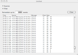
(Note that because the TT Pad and D-Beam modes are patch parameters, if you are recording and you have send sysex enabled in the V's system parameters, when you change modes, it will send a sysex. When played back, the sysex will cause the mode to change and you'll see that on the panel. However, because the controller data is specific to the mode it was recorded in and not the mode at playback time, these mode changes at playback will have no effect. You can delete these sysexes if you want.)
Some more notes on the MIDI behavior of the Time Trip pad:
- Although the pad operates in R-theta coordinate space when in Time Trip mode, it sends the MIDI data in this mode as X-Y coordinates. This is rather unfortunate because editing the data in a sequencer, and getting the behavior you want, is a non-trivial task. If anybody is really really interested, I'll sit down and work out the trig formulas for it.
- A value of 0 in one of the TT Pad CC messages means that the pad is not being touched. When the pad is touched, both CC messages (for whichever mode is active) transmit with non-zero values.
- The TT Pad Hold button does not send any MIDI itself. It causes the last touched position on the pad to be held, as if you still had your finger on the pad at that point, and this is reflected in the MIDI data. (If send sysex is enabled in the system parameters, it will send a sysex when Pad Hold is turned on and off. This will not effect playback, but it could leave Pad Hold on when you don't want it to. It might be a good idea to delete these sysexes.)
In addition to the controller types listed above, the V also receives and processes data for the following controller numbers:
| MIDI Standard Name | CC # |
| 05 | Portamento Time |
| 06/38 | Data Entry |
| 07 | Volume |
| 65 | Portamento |
| 66 | Sostenuto |
| 91 | Effect Level 1 (controls Reverb level) |
| 93 | Effect Level 3 (controls Chorus level) |
| 100/101 | RPN Number |
Clock Source
The clock source used by the arpeggiator, and by LFOs that have been synced to tempo, can be internal or external. When external clock is selected, the V expects to receive MIDI Clock (not MIDI Time Code) from a sequencer or other external source. Regardless of whether the source is internal or external, the V can also be set to output MIDI Clock. These settings are in the system parameters.
Patch Selection and Program Change Messages
Since the V has 512 patch memory slots, it obviously requires using Bank Switch messages in order to be able to select any patch via MIDI. Patch memory is divided into four banks, with patches 0-127 in bank 0, patches 128-255 in bank 1, and so on. For some odd reason, bank changes require sending a Bank Select MSB message (CC #0) with a value of 87, followed by a Bank Select LSB message (CC #32) with a value in the range 0-3 to select the desired bank. The V will transmit Bank Select and/or Program Change messages whenever a patch is selected, if such is enabled in the system settings; Bank Select and Program Change can be enabled and disabled individually. Note that when the bank and patch buttons on the panel are used to select a patch, the transmitted MIDI messages will reflect the number of the assigned patch, not the bank/patch number of the button pressed.
Parts and Multitimbrality
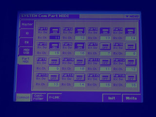
The V is sort-of multitimbral and allows for up to 16 parts. Every part can be assigned to a different channel, or parts can be doubled up on a channel. Unneeded parts can be disabled. We say the V is sort-of multimbral because the effects settings for all parts are determined by the patch that is loaded in part 1. Additionally, the panel can only display and edit the patch parameters for part 1. (Unlike, say, the JD-800 which has buttons to select which part is in control of the panel... I wonder why this wasn't implemented on the V.) Part setup is in the system parameters. Below is an image of the part setup screen. In this setup, I have parts 1-6 set up to operate on MIDI channels 11-16 respectively, and the rest of the parts are disabled.
USB
The V's USB connection can be configured to operate in one of two modes at any given time: MIDI mode or storage mode. In MIDI mode, the V can transmit and receive MIDI messages via the USB. This mode is pretty straightforward. On the Mac, the V appears as a MIDI device named "Roland V-Synth" which shows up in Audio MIDI Setup and sequencer applications. The only parameter available is a switch marked "USB MIDI THRU" that shows up on the V's USB configuration screen (you press the "USB SETUP" button under the "MIDI USB" tab on the system screen). The diagrams in the manual are pretty confusing, but I think the way it works is this: When this switch is off, the USB and the MIDI jacks act in parallel; the V can be controlled by either. When the switch is on, the MIDI jacks on the V can be used as an interface to another MIDI device. Everything that comes in over the USB will be repeated out the MIDI Out jack, and the V will merge data from the MIDI In jack into the MIDI stream sent out over the USB. In theory, you could use this to connect another synth to your system, but I suspect that the timing would not be great. However, it could be handy for a MIDI-controlled effect or something else for which timing is not critical. Note that I'm getting all of this from the manual; I have not actually tried the USB Thru mode.
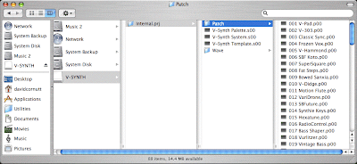
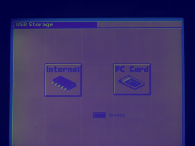
Storage mode provides direct access to the V's file system storage. In this mode, the V mounts as an external disk on the computer that it is connected to. I've tested it with both a PC running Windows Vista, and a Mac running OSX 10.4, and it works well on both. To access storage mode, first the computer must be on and the USB cable connected. Go to the mode menu and select USB mode. The next screen will allow you to choose whether the V's internal memory or the plugged-in PC card is to appear as a mounted drive at the computer. Once the selection is made, the V will attempt to connect; if it works, the drive icon will appear at your computer. The V must remain at this screen as long as the drive is mounted at the computer; you can't do anything else with the synth while storage mode is active. The manual cautions that you must not let the computer sleep or hibernate while storage mode is active. From the computer, you can copy files in either direction. This lets you make copies of the synth's files for backup or swapping out; load patches into the synth; and load sample files for importing as PCM waveforms. The manual says not to delete or rename the V's files from the computer -- use the disk mode's tools function on the V to do that. Below is an example of the V's internal flash memory, mounted as a drive on a Mac running OSX 10.4.11:
You have to install a driver from Roland before you can use either USB mode. Drivers for both Windows and MacOS are available. If you got the original CD with your V, they are on there, but it would be a good idea to check with the Roland Web site for updated versions. I tried the Mac driver and it works; there's nothing fancy, but it works. The driver's release notes do say that the driver cannot recover from a sleep, so when the V is connected, the Mac's system settings must be set up to prevent the computer from sleeping. If you are only using storage mode, this normally won't be a problem since you will generally only be using the USB connection for a few minutes at a time (since you can't play the synth while the USB is active in storage mode). I have not tried the Windows driver.
To set up the USB connection in storage, you connect the cable, go to the mode screen, choose USB, and then (if you have a PC Card in the rear panel slot) choose whether you want the computer to access the V's internal flash memory, or the PC card. After a few seconds, the chosen storage appears as a new drive on your computer; its name will be "V-SYNTH" if you are mounting internal memory, or the name that the card was formatted with ("PC CARD" by default) if you are mounting the card. To terminate the connection, or change to the other storage, use the computer's method for ejecting the drive. Once the drive is ejected, you can press the EXIT button on the V to leave USB mode, or choose one of the two storage spaces to mount again. Sometimes, to re-mount, you have to disconnect and reconnect the USB cable, and sometimes you don't. I haven't figured out what causes that. Currently I have my V connected to a short USB cable which then plugs into a USB extender, and I disconnect and reconnect when needed at the extender.
To set up the USB connection in storage, you connect the cable, go to the mode screen, choose USB, and then (if you have a PC Card in the rear panel slot) choose whether you want the computer to access the V's internal flash memory, or the PC card. After a few seconds, the chosen storage appears as a new drive on your computer; its name will be "V-SYNTH" if you are mounting internal memory, or the name that the card was formatted with ("PC CARD" by default) if you are mounting the card. To terminate the connection, or change to the other storage, use the computer's method for ejecting the drive. Once the drive is ejected, you can press the EXIT button on the V to leave USB mode, or choose one of the two storage spaces to mount again. Sometimes, to re-mount, you have to disconnect and reconnect the USB cable, and sometimes you don't. I haven't figured out what causes that. Currently I have my V connected to a short USB cable which then plugs into a USB extender, and I disconnect and reconnect when needed at the extender.
The V stores all of the patches and PCM waveforms in a file structure called a "project folder". The top-level project folder contains several system files, and two sub-folders. One of the sub-folders contains all of the encoded PCM waveforms. The other contains patches, one per patch file, in one of two formsts: either a WAV file, or a proprietary format with a file name ending with a ".w00" extension. (I think only the factory-supplied ones use the ".w00" format; from what I've seen, all user-created ones remain as WAV files.) Note that one of the system files contains all of the system mode settings, which means that when you load a new project, your system settings may change.
The V has internal flash memory storage for a single project, with some amount of space for wave files; as I figure it there's storage for about 125 seconds' worth of stereo waves at the 44.1 KHz rate. There is actually 16 MB of internal flash, but the system only allows one project folder to be stored there at a time, and it must be named "Internal.prj". (I've tried copying in project folders with other names into the internal memory via USB; it lets you do the copy if there's enough space remaining, but the disk tools project load screen won't let you load it. The manual does say that this is the way it works, but there is no reason why that is obvious to me.) However, there is also a PC Card (PCMCIA) slot on the back where you can insert a memory card. The memory cards can hold multiple projects, and the folders can be named anything that ends with the ".prj" extension. Both the internal flash and the memory cards can also store WAV files that aren't in a project, for importing. You can replace a project, in either internal memory or on the card, by copying over it with another project folder of the same name via the USB connection. I think you can also swap around individual patch files, although I have not yet experimented extensively in this area. The name of each patch file begins with a three-digit number that determines what its slot number will be when the project loads; the rest of the file name is the visible patch name. I believe you can copy in patch files into the patch folder inside the project folder to add patches to a project. However, to rename or delete individual patches, you have to do that from the V's disk tools; according to the manual, you can't do that directly from the computer.
The project files provide, among other things, a way to organize patches and waves by song, by session, or any other way you want to do it This means that, for example, you don't have to have every single wave file in your possession in the V all the time; you can organize projects so that only the waves you need for a given set of patches are present in a given project folder. Only one project at a time can be loaded. When you power up the V, it loads "internal.prj" from internal flash, and that's what you see when the screen first comes up. You can go to the disk tools to load a different project, or to re-load the current project. You're probably wondering how patch edits get saved, what with all these project files running around. The answer is that, when you load a project, the V remembers what project is loaded. When you save a patch, it re-writes the patch file inside that project, in addition to holding the edits in a working area where the current project is held. The same goes for editing waves. However, you can also save the entire project from the disk tools screen. This saves every file in the project. This is in fact what you must do when you edit the patch pallettes; unlike patches and waves, they don't save back to the project automatically. Note that if you make "back-door" changes to the currently loaded project, using the USB connection or by swapping out the PC Card, these won't appear in working memory until you manually re-load the project from the disk tools screen.
Importing samples can easily be done in USB storage mode. Samples to be imported must be in WAV format, which nearly every piece of DAW software and OS can now produce (yes, you can export WAV files on a Mac too, with Quicktime). Once you have the V-Synth mounted, copy the WAV files you want to import into the top level of the project folder (not into one of the subsidary folders). Once you've done this, eject the V-Synth disk icon. You can then go to the V-Synth's screen, exit USB mode, go into sample mode, and select "Import". You will see a list of files from the top level of the project folder, from which you can select one of the WAV files you copied in for editing and encoding. Once you have encloded the sample, you can delete the WAV file. Exit sample mode, go to disk mode, and into the disk tools function. Select the Delete mode, and then choose and confirm each file to be deleted. Be careful not to delete any of the system files -- if you do, you may have to perform a factory reset.
I'll leave you with this image of the USB storage mode screen:
Next time, we'll take a look under the panel and see what the V's guts actually consist of. I'm not sure when I will get that installment done -- it may be a while. Look soon for pics of my new rec-room studio, which is the reason it took me so long to get this installment done.
Sunday, June 15, 2008
Inside the V-Synth, Part 4
In this installment, we'll look at one of the V-Synth's most outstanding assets -- its performance controls.
Starting With The Basics
The V-Synth's keyboard and bend lever are pretty typical for most Roland models since the late '80s. The five-octave keyboard, C to C, is one of the better synth-weighted keyboards. The keys are full size, have enough travel but not too much, and the stop blocks are just well enough damped. The keyboard is pressure (channel aftertouch) sensitive, and while this tends to be on the heavy side, it doesn't appear to suffer from the pressure sensor degredation of earlier Roland models. Of course, velocity and release velocity are sensed, although I haven't found anything that the V does with release velocity. (The system mode provides sensitivity adjustments for both velocity and aftertouch.) The key edges are blunted just enough to prevent glissandos from being painful, although the black keys do stand a bit high for the purpose. The white key ends have lips of about 1/8-inch, which do not overhang the lower front edge of the case (unlike some earlier Roland models).
The V has Roland's characteristic T-handle combined pitch bend and modulation control. Rocking it left or right affects pitch bend. (The amount of bend is a patch parameter; up and down can be set to different ranges.) It returns to zero reliably without a noticable center detent. Pushing the stick towards the back of the synth adds modulation (which is a routable parameter via the control matrix, explained below). It is spring-loaded in both axes. The modulation axis has a lot of travel compared to most other Roland synths I've played.
Patch Selection and Storage
Many Rolands have a set of eight "bank" and eight "patch" buttons, allowing for eight patches to be selected with a single button press, and 64 patches accessible in a maximum of two button presses. However, the V-Synth has far more patch memory than that -- 512 patch locations. Roland came up with a clever way of addressing this. At the patch main screen, on the left side of the screen is a "List" button. Through this, you can access all patches, in numerical order or by category.
However, 64 patches can be assigned as "favorite" patches, accessible from the patch buttons in addition to the on-screen list. The patch buttons are shown below:

Holding down the assign button and pressing one of the 1-8 buttons assigns the current patch to that button in the current bank. (Note that this does not effect patch memory; the patch remains where it was in the on-screen patch list.) To change banks, hold down the bank button and press one of the 1-8 buttons. If you forget what bank you are on, hold down the bank button and the appropriate 1-8 button will flash; also, the screen will display the names of the eight patches assigned to that bank.
Note that all patches, as well as all PCM sounds and samples on board, are stored in a larger overarching structure called a "project". We'll have more to say about this in the next installment.
Keyboard Transpose
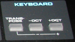
The Keyboard Transpose buttons can transpose the keyboard any desired number of half steps, or quickly transpose by octaves. The latter can be handy when you need to shift the range of the keyboard, say, for a bass or lead patch. These are shown below:
Volume Controls
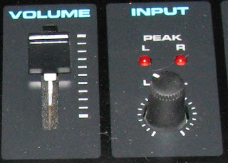
The master volume controls the output levels of all outputs, including the direct outs and the digital outputs. The external input level knob controls the level of any signal coming in through the external inputs; a red LED indicates clipping. (There are also input preamp gain knobs on the rear panel.) These are shown below:
Programmable Knobs
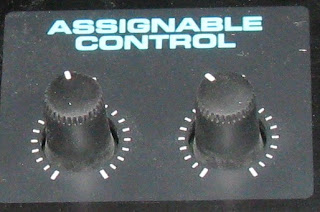
These two knobs can be programmed in the control matrix to provide real-time control over any desired parameter. One thing to note about them is that, unlike the patch editing knobs, the programmable knobs are "live" the moment a patch is selected; if the knobs are not centered, the parameters they control will be effected immediately. Further, these knobs do not edit the patch; they are like MIDI controllers in that respect. (In fact, they are MIDI controllers. They can be set to transmit MIDI CC messages.) The programmable knobs are shown below:
The Cool Toys: Time Trip Pad
Having gone through the undercard, we now come to the main event. What's the first thing that catches the eye of everyone seeing a V-Synth for the first time? Yes, it's the Time Trip Pad! So how does it work? What does it do? And how about that weird slot in the top of the case labeled "D-Beam"?
The Time Trip pad operates in one of two modes: Time Trip mode, and assignable (or "X-Y") mode. In Time Trip mode, the pad operates in a polar, or R-theta mode. You operate it by placing your finger somewhere on the outer circle, and moving it in a clockwise or counterclockwise direction, quickly or slowly (or you can stop). When you do so, you are taking direct control of the time aspect of the Variphrase processing. Recall that Variphrase makes pitch and time independent parameters. When you touch the pad, time freezes. Moving your finger in a clockwise circle causes time to advance, at the speed you move at. A typical example used to demonstrate it is to set up a patch with a basic vocal sample. Touching the pad and moving your finger in a slow clockwise circle causes the vocal sample to proceed as if the person who was sampled was speaking
veeeeeeeeeerrrrrrrrrrrryyyyyyyyyy
sloooooooooooowwwwwwwwllllllllllyyyyyyyy.
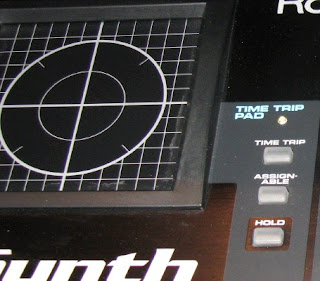
Moving your finger in a fast circle causes the vocal sample to be renderedveryfast! The effect is quite different from rocking a tape reel or scratching on a phoograph because the tone of voice of the sample remains normal. If you go very slowly, you can hear individual sibiliants, clicks, thumps, and transient vowel sounds and vocalizations that we don't normally consciously hear in speech. The effect is quite weird. Moving your finger in a counterclockwise circle causes time to go backwards, so in the case of our vocal sample, it will sound like a reversed tape. Here is the Time Trip pad and its mode buttons:
When you take your finger off the pad, time reverts to advancing normally, unless you have engaged the "Hold" switch to the right of the pad. In this case, the pad retains the last position touched until you touch it again, meaning that time will "freeze" when you take your finger off the pad.
In the Time Trip mode, an additional parameter of your choice can be controlled by how far away your finger is from the center of the pad. This is set up in the control matrix (discussed further down).
When Assignable mode (often referred to as "X-Y" mode in the patch editing screens) is selected, the pad controls two parameters of your choice. One parameter is effected by vertical movement of your finger, the other by horizontal movement. You select which two parameters you want to control in the control matrix. The zero position of the pad is determined by how you set up the parameters in the matrix; normally, this will be the center of the pad, but you can set it up differently if you want. Whenever you take your finger off the pad, the parameters being controlled will revert to zero unless the Hold button is on; in this case, the pad will remember the last position touched until it is touched again.
In either mode, the blue light next to the pad will light whenver the pad is controlling something, either because it senses a touch, or because Hold is on.
The Control Matrix
All of the V-Synth's real-time controllers -- keyboard aftertouch & velocity, the modulation axis of the bend lever, the assignable knobs, the R dimension of the Time Trip pad, the X and Y dimensions in the X-Y mode of the pad, and the assignable mode of the D-Beam -- are routed to parameters via the control matrix. The matrix has eight source slots, each of which has two destination slots. To set up a routing, you pick an empty source slot and choose a source. Then, you can choose one or two destinations and set the sensitivity of each. There are about 75 possible destinations, so I won't list them here; download the manual from Roland if you're interested. The sensitivity effects how much the controller effects the destination parameter, in either direction; it can be set positive or negative.
In order to record MIDI from the real-time controllers (other than aftertouch and velocity), each controller is assigned to a MIDI Continuous Controller number in the system mode settings. Although it is possible to select a MIDI CC number directly as a source in the control matrix, it will probably be less confusing to use the CC numbers assigned to the controllers. This will be covered in Part 5.
Until Next Time
The next installement, Part 5, will cover all aspects of the V-Synth's audio and MIDI I/O. There are aspects of how the controllers, the arpeggiator, and MIDI interact that aren't well explained in the manual. I'll be doing some research and experimenting on these. Also covered in Part 5 will be the V's USB interface, which is quite powerful but requires some care in setup and use. I'll go through how the V structures its internal storage and show you how to use the USB without fouling up the operating system.
Starting With The Basics
The V-Synth's keyboard and bend lever are pretty typical for most Roland models since the late '80s. The five-octave keyboard, C to C, is one of the better synth-weighted keyboards. The keys are full size, have enough travel but not too much, and the stop blocks are just well enough damped. The keyboard is pressure (channel aftertouch) sensitive, and while this tends to be on the heavy side, it doesn't appear to suffer from the pressure sensor degredation of earlier Roland models. Of course, velocity and release velocity are sensed, although I haven't found anything that the V does with release velocity. (The system mode provides sensitivity adjustments for both velocity and aftertouch.) The key edges are blunted just enough to prevent glissandos from being painful, although the black keys do stand a bit high for the purpose. The white key ends have lips of about 1/8-inch, which do not overhang the lower front edge of the case (unlike some earlier Roland models).
The V has Roland's characteristic T-handle combined pitch bend and modulation control. Rocking it left or right affects pitch bend. (The amount of bend is a patch parameter; up and down can be set to different ranges.) It returns to zero reliably without a noticable center detent. Pushing the stick towards the back of the synth adds modulation (which is a routable parameter via the control matrix, explained below). It is spring-loaded in both axes. The modulation axis has a lot of travel compared to most other Roland synths I've played.
Patch Selection and Storage
Many Rolands have a set of eight "bank" and eight "patch" buttons, allowing for eight patches to be selected with a single button press, and 64 patches accessible in a maximum of two button presses. However, the V-Synth has far more patch memory than that -- 512 patch locations. Roland came up with a clever way of addressing this. At the patch main screen, on the left side of the screen is a "List" button. Through this, you can access all patches, in numerical order or by category.
However, 64 patches can be assigned as "favorite" patches, accessible from the patch buttons in addition to the on-screen list. The patch buttons are shown below:
Holding down the assign button and pressing one of the 1-8 buttons assigns the current patch to that button in the current bank. (Note that this does not effect patch memory; the patch remains where it was in the on-screen patch list.) To change banks, hold down the bank button and press one of the 1-8 buttons. If you forget what bank you are on, hold down the bank button and the appropriate 1-8 button will flash; also, the screen will display the names of the eight patches assigned to that bank.
Note that all patches, as well as all PCM sounds and samples on board, are stored in a larger overarching structure called a "project". We'll have more to say about this in the next installment.
Keyboard Transpose
The Keyboard Transpose buttons can transpose the keyboard any desired number of half steps, or quickly transpose by octaves. The latter can be handy when you need to shift the range of the keyboard, say, for a bass or lead patch. These are shown below:
Volume Controls
The master volume controls the output levels of all outputs, including the direct outs and the digital outputs. The external input level knob controls the level of any signal coming in through the external inputs; a red LED indicates clipping. (There are also input preamp gain knobs on the rear panel.) These are shown below:
Programmable Knobs
These two knobs can be programmed in the control matrix to provide real-time control over any desired parameter. One thing to note about them is that, unlike the patch editing knobs, the programmable knobs are "live" the moment a patch is selected; if the knobs are not centered, the parameters they control will be effected immediately. Further, these knobs do not edit the patch; they are like MIDI controllers in that respect. (In fact, they are MIDI controllers. They can be set to transmit MIDI CC messages.) The programmable knobs are shown below:
The Cool Toys: Time Trip Pad
Having gone through the undercard, we now come to the main event. What's the first thing that catches the eye of everyone seeing a V-Synth for the first time? Yes, it's the Time Trip Pad! So how does it work? What does it do? And how about that weird slot in the top of the case labeled "D-Beam"?
The Time Trip pad operates in one of two modes: Time Trip mode, and assignable (or "X-Y") mode. In Time Trip mode, the pad operates in a polar, or R-theta mode. You operate it by placing your finger somewhere on the outer circle, and moving it in a clockwise or counterclockwise direction, quickly or slowly (or you can stop). When you do so, you are taking direct control of the time aspect of the Variphrase processing. Recall that Variphrase makes pitch and time independent parameters. When you touch the pad, time freezes. Moving your finger in a clockwise circle causes time to advance, at the speed you move at. A typical example used to demonstrate it is to set up a patch with a basic vocal sample. Touching the pad and moving your finger in a slow clockwise circle causes the vocal sample to proceed as if the person who was sampled was speaking
veeeeeeeeeerrrrrrrrrrrryyyyyyyyyy
sloooooooooooowwwwwwwwllllllllllyyyyyyyy.
Moving your finger in a fast circle causes the vocal sample to be renderedveryfast! The effect is quite different from rocking a tape reel or scratching on a phoograph because the tone of voice of the sample remains normal. If you go very slowly, you can hear individual sibiliants, clicks, thumps, and transient vowel sounds and vocalizations that we don't normally consciously hear in speech. The effect is quite weird. Moving your finger in a counterclockwise circle causes time to go backwards, so in the case of our vocal sample, it will sound like a reversed tape. Here is the Time Trip pad and its mode buttons:
When you take your finger off the pad, time reverts to advancing normally, unless you have engaged the "Hold" switch to the right of the pad. In this case, the pad retains the last position touched until you touch it again, meaning that time will "freeze" when you take your finger off the pad.
In the Time Trip mode, an additional parameter of your choice can be controlled by how far away your finger is from the center of the pad. This is set up in the control matrix (discussed further down).
When Assignable mode (often referred to as "X-Y" mode in the patch editing screens) is selected, the pad controls two parameters of your choice. One parameter is effected by vertical movement of your finger, the other by horizontal movement. You select which two parameters you want to control in the control matrix. The zero position of the pad is determined by how you set up the parameters in the matrix; normally, this will be the center of the pad, but you can set it up differently if you want. Whenever you take your finger off the pad, the parameters being controlled will revert to zero unless the Hold button is on; in this case, the pad will remember the last position touched until it is touched again.
In either mode, the blue light next to the pad will light whenver the pad is controlling something, either because it senses a touch, or because Hold is on.
Here is a demonstration of the Time Trip pad being used on a vocal sample. The patch has the vocal sample on OSC 1; OSC 2 is off. COSM 1 has a comb fiter selected; COSM 2 is off. The R parameter of the Time Trip pad is controlling the center frequency of COSM 1; you can hear this when I move my finger closer to the center of the pad. At about 1:40, I engage the hold switch. The squealing noise heard in places is an artifact of the low-quality sample.
D-Beam
The D-Beam is an infrared range sensor; it senses how close your hand (or any other object over the panel) is to the sensor. The distance is translated into a value for a control parameter. The sensors are buried in a slot in the panel, with big blue LEDs on either side of it. Depending on the calibration, the D-Beam will trigger whenever an object is 18-24 inches (45-60 cm) above the slot. Note that this may be a problem if you set up the V-Synth on a multi-keyboard stand with another keyboard above it; the D-Beam will sense the bottom of the keyboard above. (I'm having this problem right now; my D-Beam is picking up the bottom of the Juno-106 on the tier above. And I've got that tier as high up as it will go on the stand. I don't want to put the V-Synth on top because the touch screen will be hard to read if it's up too high.) The manual mentions that the useable range may be reduced if the sensor is exposed to direct sunlight. I haven't tried that; I do have the V right in front of a window, and light coming in has not caused a problem. The D-Beam and its mode buttons are pictured below:

Many players who have played with a V-Synth in the store may not realize, and it isn't well explained in the manual, that there are actually two sensors in that little slot. The beams are pretty close together, so just moving your hand randomly over the slot is likely to activate both of them. You have to stay over to the side to only activate one sensor. You can tell when you are doing it right because only the blue LED on that side will light. Operating both sensors independently, with one hand, is a bit of a feat. I've had some success with holding my hand with my index and pinky fingers extended, while the middle and ring fingers are curled in (the "devil's horns" hand sign) and rotating my wrist this way and that to change the relative distances of the two fingers above the sensors.
The D-Beam has four operating modes, which I'm going to address out of order for clarity. The Pitch mode make the D-Beam a pitch bend control. Being that it's a unidirectional sensor, it can only bend in one direction, either up or down depending on how you set it up in the patch. However, if your patch is using PCM oscillators with stereo samples, the two sensors will bend the left and right channels independently, which is pretty cool. The second mode is Time, which instead of pitch bending performs time bending. As you move closer to the sensor, time slows down, while pitch is maintained thanks to Variphrase. Again, if you are using stereo PCM waveforms, the two sensors will operate on the left and right channels independently.
The Assignable mode sets up the two sensors to control two parameters of your choice, per your selections in the control matrix. The Time Trip mode, like the Time Trip pad, is motion rather than position sensitive. To make time advance, you move your hand towards and then away from the sensor cyclically. This is kind of difficult; there is a "turning point" at each end of the travel that you have to reach. If you don't, then when you reverse direction, time will go backwards. I'm not sure how useful this is, considering that the Time Trip pad provides the same effect and is easier to control. Unlike the pad, the D-Beam does not have a hold function.
Arpeggiator
An old favorite that went away a long time ago returns: the arpeggiator. Analolg old-timers will recall that the old Jupiters and Junos (up to the Juno-60) offered an arpeggiator that allowed the performer to hold a chord on the keyboard and the synth would play an arpeggiation of the notes held. The effect was commonly used in the late '70s and early '80s; among other things, it provided a way to simulate the analog step sequencers found on the large modular systems of the day. Here are the arpeggiator panel controls:

Well, this isn't your Juno-60's arpeggiator. The simple front panel controls disguise just how sophisicated the V's arpeggiator is. The on/off button is obvious; it enables or disables the arpeggiator. The knob controls the rate. The hold button causes the arpeggiator to "lock on" to any note struck, even after the note is released. What this is good for will be explained momentarily.
The real capabilities of the arpeggiator are in the patch settings, accessible through the touch screen. The arpeggiation can run a number of different patterns, or "motifs": ascending, descending, alternating, random. It can also arpeggiate the notes in the order that you struck the keys. These do pretty much what you expect. However, you can also build your own patterns, and it's here where some of the power becomes evident. In a user pattern, all notes in the pattern need not have the same time value. Duration as a percentage of the note value can be controlled, and tied/slurred notes can be set up. Rests can also be inserted. Two special motifs that can be used with a user pattern are the fixed motif, in which the pattern actually specifies a fixed sequence of notes (used with drum kit patches), and a motif in which a held key specifies what key the pattern plays in. You can also limit the range of the keyboard over which the arpeggiator operates. This is where the arpeggiator hold button becomes useful: you can play an arpeggiation, hold it, and then play a lead or some other part on the part of the keyboard that is excluded from the arpeggiator, while the arpeggiation continues to run. The default rate is a patch parameter, or you can set it up to sync the arpeggiation to received MIDI Clock messages.
V-Link
The V-Link provides the ability to control an Edirol video pattern generator and display system by what is played on the synth. The intent is to provide synchronized audio and video performances, a concept that flashes back to the late '60s when concerts were frequently accompanied by visuals from slide or film projectors creating abstract patterns. I don't have one of the Edirol video generators, so I can't say much else about V-Link. I will note that, from reading the description in the manual, it appears to take over the MIDI Out port when it is on.
The Missing Button: Portamento
The V has a good portamento capability. All portamento parameters are stored with the patch. Constant-time and constant-rate modes are available; up and down times are independently settable, and a legato mode is available which activates the portamento only when playing legato. So what's missing? There is no button on the panel to turn portamento on and off. I think this is the first synth I've ever seen which had portamento but no panel control for it. To turn it on or off, you have to go into the patch parameters.
Using Your Feet
The V has a hold pedal input and not one but two expression pedal inputs. The hold jack can be set up for either a normally-closed pedal (Roland's standard) or a normally-open pedal (nearly everyone else's standard) in the system settings.
The Control Matrix
All of the V-Synth's real-time controllers -- keyboard aftertouch & velocity, the modulation axis of the bend lever, the assignable knobs, the R dimension of the Time Trip pad, the X and Y dimensions in the X-Y mode of the pad, and the assignable mode of the D-Beam -- are routed to parameters via the control matrix. The matrix has eight source slots, each of which has two destination slots. To set up a routing, you pick an empty source slot and choose a source. Then, you can choose one or two destinations and set the sensitivity of each. There are about 75 possible destinations, so I won't list them here; download the manual from Roland if you're interested. The sensitivity effects how much the controller effects the destination parameter, in either direction; it can be set positive or negative.
In order to record MIDI from the real-time controllers (other than aftertouch and velocity), each controller is assigned to a MIDI Continuous Controller number in the system mode settings. Although it is possible to select a MIDI CC number directly as a source in the control matrix, it will probably be less confusing to use the CC numbers assigned to the controllers. This will be covered in Part 5.
Until Next Time
The next installement, Part 5, will cover all aspects of the V-Synth's audio and MIDI I/O. There are aspects of how the controllers, the arpeggiator, and MIDI interact that aren't well explained in the manual. I'll be doing some research and experimenting on these. Also covered in Part 5 will be the V's USB interface, which is quite powerful but requires some care in setup and use. I'll go through how the V structures its internal storage and show you how to use the USB without fouling up the operating system.
Friday, June 13, 2008
TOSLink
The next post in the V-Synth series is coming tomorrow. As soon as I find a mic that works so I can make a demo sample. In the meantime, here's another aspect: The synth, like a lot of modern ones, has digital I/O. This comes in the form of both standard S/PDIF coax connectors, and TOSLink optical connectors. Since my MOTU 828 Mk I audio interface also has digital I/O, I decided that I wanted to be able to run the V-synth straight into it, so that I don't always have to allocate two channels for the V on the mixer.


Just for the heck of it, I decided to go with TOSLink (which is basically the S/PDIF protocol on fiber) instead of the coax. I've never had a chance to play with TOSLink before. So I bought an optical cable and hooked it up. And once it dawned on me that the synth and the 828 can't sync if they're both on internal clock (duh), it worked fine. It's kind of cool to have a laser in your synth:
Here's a less artistic but clearer shot of the cable connector.
That little metal tip contains the fiber end. It looks round in the photo, but if you were to look at it closely it's actually D-shaped. The socket it goes into is also D-shaped, so it has to be rotated the right way in order to plug in.
Subscribe to:
Posts (Atom)